Lecture
Flat phased antenna arrays (PAR). Features of construction. Analysis of the pattern.
17.1. PHAR construction schemes
Phased antenna arrays are characterized by the inclusion of phase shifters or switches in the antenna path of the system.
controlling the phase or amplitude-phase distribution for electrical scanning. Found the use of various schemes for building PAR
from system requirements. Spatial excitation method (also called optical type distributor) allows two
Antenna version: reflective PAR (Fig. 17.1, a) and passing PAR (Fig. 17.1, b).
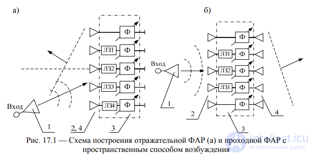
_img_351.jpg) Fig. 17.1 - Diagram of the construction of the reflective PARA (a) and the
Fig. 17.1 - Diagram of the construction of the reflective PARA (a) and the
The feeder excitation method (closed-type distributor) allows for sequential, parallel, binary-floor (herringbone) powering of emitters and phase shifters and their combination (Fig. 17.2).

_img_352.jpg) Fig. 17.2 - Serial scheme (a) and binary-floor scheme (b) of excitation of the primary emitters of phased arrays
Fig. 17.2 - Serial scheme (a) and binary-floor scheme (b) of excitation of the primary emitters of phased arrays
Hybrid antennas are being used - sharing of headlamps and optical-type antennas. In fig. 17.3 is a diagram of a hybrid mirror antenna (low-element PHAR and focusing mirror), which allows electrical
scanning in a limited sector of angles with high directivity of action.
_img_353.jpg)
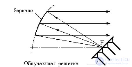
Fig. 17.3 - Hybrid Mirror Antenna Scheme
The cylindrical array of emitters, connected by switches (with or without phase shifters) to the stripline excitation system,
waveguides, radial waveguides and other elements, allows you to scan in a wide angle sector (Fig. 17.4).
_img_354.jpg)
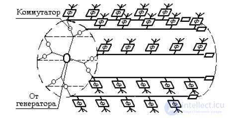
Fig. 17.4 - Diagram of a cylindrical headlight with a system of switches and phase shifters
It is possible to use multipath antennas that form several DNs from one radiating aperture, each of which corresponds to an input antenna path.
A multi-channel switch connected to the inputs of a multipath antenna allows discrete movement of the beam in space.
in accordance with the characteristics of a multi-beam antenna.
The need to use a multipath mode in radio systems leads to the creation of a phased array with several independent scanning beams. A possible way to solve such problems is to combine multipath antennas with a system of controlled phase shifters and excited main waveguides via directional taps (Fig. 17.5).
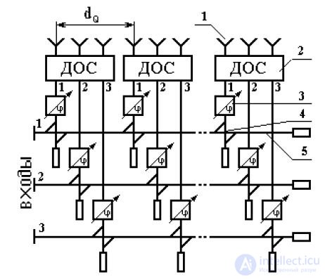
_img_355.jpg) Fig. 17.5 - HEADLIGHTS with one radiating aperture and three independent beams
Fig. 17.5 - HEADLIGHTS with one radiating aperture and three independent beams
Each of the above schemes for constructing the HEADLIGHTS has its advantages and disadvantages, and the choice of this or that scheme is determined by the set requirements for the radio system, the subsequent processing of the microwave signal, and the element base.
The MA with the radiating part in the form of a lattice includes the so-called diagram-forming circuit (DOS), which connects all the radiator emitters to all the antenna inputs. Currently, various types of DOS are known: parallel, sequential, reactive, heat loss, matrix, etc. DOS for various types of gratings (linear, flat, ring, etc.), different operating frequency ranges and different requirements for the directivity characteristics of the rays were developed. The most common are dshekhemy: a scheme with parallel wiring power emitters, called the matrix Butler scheme or abbreviated Butler matrix (Fig. 17.6, a), and the scheme with serial wiring, called the Blass matrix (Fig. 17.6, b).
_img_356.jpg)
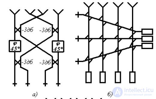
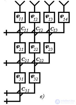
a) matrix Butler; b) Blass matrix; c) modified dos blas
Fig. 17.6 - Dagmoobrazoobrazuyuschimi multi beam antenna
The Butler matrix is assembled on the basis of three-channel directional couplers (bridges) and static (fixed) phase shifters and is used for gratings with a binary number of radiators: N 2 n 1,2,3,. The lattice forms a family of N rays, symmetric with respect to the normal. The isolation between the inputs is provided by the properties of bridge connections when matching the emitters and the rest of the path. The Butler matrix contains log 2 N N
_img_357.jpg) 2 phase shifters. The Blass matrix uses a larger number of directional couplers, matched loads, additional losses, and supply lines of various lengths. Different phase distributions for partial beams in DOS Blass (of the sequential type) are realized due to different angles of inclination of the horizontal transmission lines (Fig. 17.6, b). The Blass matrix allows using a different number of emitters and amplitude distributions falling to the edges, as well as reducing the number of inputs compared to the Butler matrix. There are various modifications of DOS serial and parallel types. Thus, the modified DOS Blass eliminates consistent loads, reduces the length of transmission lines by turning on phase shifters (Fig. 17.6, c). A common disadvantage of IDA on the basis of DOS is the presence of a large number of bridge devices, static phase shifters and complex branched feeder devices.
2 phase shifters. The Blass matrix uses a larger number of directional couplers, matched loads, additional losses, and supply lines of various lengths. Different phase distributions for partial beams in DOS Blass (of the sequential type) are realized due to different angles of inclination of the horizontal transmission lines (Fig. 17.6, b). The Blass matrix allows using a different number of emitters and amplitude distributions falling to the edges, as well as reducing the number of inputs compared to the Butler matrix. There are various modifications of DOS serial and parallel types. Thus, the modified DOS Blass eliminates consistent loads, reduces the length of transmission lines by turning on phase shifters (Fig. 17.6, c). A common disadvantage of IDA on the basis of DOS is the presence of a large number of bridge devices, static phase shifters and complex branched feeder devices.
_img_358.jpg)
scheme. The number of bridge devices MM, depending on the number of beams N formed, is determined by the following expressions: for a complete and modified Blass matrix
2 bridges and log N 1N
2
2 (N N) log2 N N
respectively MM N, MM соответственно; for the Butler matrix MM .
22
The number of static phase shifters M for the Butler matrix is determined by log N 1
ratio M.
2
In fig. 17.7 these dependences are illustrated graphically. It follows from the graphs that DOS of a parallel type with the same number of input channels has the least number of elements compared to DOS of the sequential type. This is the advantage of the Butler matrix compared to the Blass matrix.
256
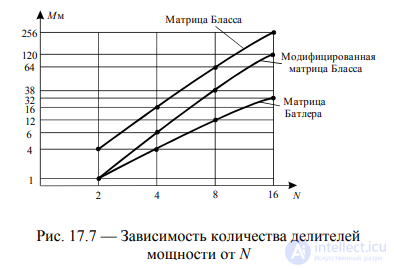
Fig. 17.7 - Dependence of the number of power dividers on N
17.2. Adaptive Digital HEADLIGHT
The basis of promising radar and radio information systems are adaptive antenna systems based on HEADLIGHTS that allow you to create multipath receiving structures that are flexible in managing their modes of operation and are well adapted to various types of interference and changing electromagnetic environment. In addition, in such systems, complex broadband signals can be processed simultaneously. In foreign literature, such antenna systems have received the name "intelligent antennas" ("intelligent antennas").
By analogy with the term “intelligent antennas” we will call such digital adaptive HEADLIGHTS - digital intelligent HEADLIGHTS or CIFAR, which are a new scientific and technical direction in radio information systems, the development of which creates the basis for a sharp, abrupt increase in the effectiveness of ground-based and space-based radar systems, radio communications, radio navigation, radio intelligence and electronic warfare.
In fig. 17.8 presents the generalized basic structure of the DIA, in which the entire array of emitters is divided into N2 modules containing N1 elements each, so that their total number is Nxy = N1N2. Such a modular partitioning simplifies the constructive and algorithmic construction of the DIET, especially with a large number of emitters in the array (about 1000 and more), but the modular structure of the DIET is quite general, because with a large number of emitters, digital signal processing is performed by the entire set of digital modules, and with a small number of emitters it boils down to one module, digital processing by which is performed in the special calculator TsIFAR.
In fig. 17.9 shows a block diagram of the transmitting part of the digital and transceiver microwave elements of the antenna-digital module with ADC and DAC. The radio service zone CIPPAR is determined by the DN of a single emitter or a DN module is formed. Transmitting and receiving amplifiers for typical radio bands (1 ... 10) GHz of promising radio information systems, made on the basis of advanced microwave - microelectronic solid-state technology, generally have rather compact dimensions, possessing high characteristics of radiated microwave power and sensitivity of receiving circuits. The transmitting and receiving modes of operation of the CIFAR can either be combined in a common transceiver element (Fig. 17.9), and their work can be separated only in time, or the receiving and transmitting grids will be separated, and their modes of operation will occur at different frequencies of signal reception and transmission.
Consider the block diagram (Fig. 17.8) of large-aperture large-module broadband radar range (10 ... 20) see. The design features of digital spatial-temporal signal processing in this radar are due to the following factors: the need to ensure high angle radar power measurement, leading to using a receiving antenna in the form of a large-aperture AR with an extremely large number of elements (several thousand and even tens of thousands), which requires the construction of large-format modules The structure of the AR and, at a minimum, a two-stage procedure for the spatio-temporal processing of signals in a given radar station, is intramodular and intermodular (Fig. 17.8); high resolution and accuracy of range measurement, i.e., the need to use wideband signals, which, combined with a large antenna size, requires compensation for group delay of signals and interference on the PAH surface in the process of spatially processing signals.
In order to simplify this processing, a two-stage procedure of adaptive spatial and space-time signal processing is used, in which the group delay of the signals is compensated only at the second processing stage (Fig. 17.8). As seen from the figure, the processing of signals is carried out in two stages: at the first stage, according to the structure of the generalized algorithm (Section 4.1), analog spatial signal processing is performed within each module (section), which is a sublattice with N1 receiving radiating elements and an adder, the number of such modules being N2 and the total number of radiating elements
Nxy N1N22;
_img_360.jpg)
_img_361.jpg)
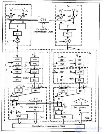
Fig. 17.8 - Block diagram of signal processing in large-aperture large-module broadband radar
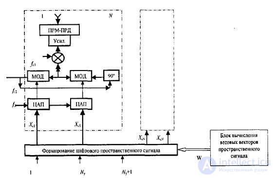
Fig.17.9 - Diagram of the transmitting part
at the second stage, digital intermodular space-time signal processing is carried out in N2 modules of the digital phased array; in this case, N2 spatial channels are processed in each module. At the first stage, by appropriate phasing of the signals from the local oscillator (Fig. 17.10), intra-modular spatial signal processing is performed.
_img_362.jpg)

Fig. 17.10 - Generation and wiring of the signals of the local oscillator
In principle, two options are possible for constructing an intra-modular (sectional) processing: adaptive noise suppression by forming “zeros” in the DN section in the direction of interference sources located in the side lobes of the DN section using information on the coordinates of the interference sources; use the usual non-adaptive procedure for managing the DN section.
17.3. Purpose and construction principle of synthesized aperture radar antenna
Synthesis of aperture is a technique that allows you to significantly increase the resolution of the radar in the transverse relative flight direction and obtain a detailed image of the radar map of the area over which the aircraft is flying.
The detail of the radar image depends on the linear resolution of the radar. In the direction radial with respect to the radar, the linear resolution, i.e. the resolution in range δR, is determined by the sounding signal, and in the transverse direction (tangential resolution) δl is the width of the radar beam and the distance to the target (Fig. 17.11). The detail of the radar image of the terrain is higher, the smaller δR and δl.
_img_363.jpg)
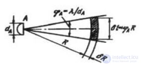
Fig. 17.11 - Parameters characterizing the detail of the radar image
Let a linear phased array of size (aperture) L (Fig. 3, a) consist of N + 1 emitters. Summing up the signals received by the irradiators, one can receive at each moment of time
PAG diagram with width a . If it takes a lot of L to provide a given φ
L is a large length of the aircraft fuselage, then it is possible to synthesize the HEADLIGHTS by sequentially moving one emitter along this aperture with some V velocity, receiving signals reflected from the target, memorizing them, and then processing them together (Fig. 17.12).
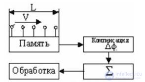
_img_364.jpg) Fig. 17.12 - Aperture synthesizing scheme for moving the irradiator
Fig. 17.12 - Aperture synthesizing scheme for moving the irradiator
In this case, the aperture of a linear antenna with an effective size L and DND of width φс = λ / L is synthesized, however, the time spent on synthesizing tc = L / V increases and the radar hardware is complicated.
17.4 PCA structural diagram
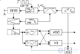
The basis of PCA is made up of coherent-pulse radars constructed according to a scheme with internal coherence (Fig. 17.13).
_img_365.jpg) Fig. 17.13 - Radar chart with synthesizing aperture
Fig. 17.13 - Radar chart with synthesizing aperture
A coherent KG generator at a frequency fpch serves to form a probing signal with a frequency f0 + fpch in a single-band modulator. The source of cokes with a frequency f0 is the GRCH. The sounding signal is modulated by a pulse sequence from the modulator M. The power amplifier of the PA is a terminal stage of the transmitter. Signal processing (memorization, phase compensation, summation) is usually performed at a low frequency. Therefore, the circuit provides quadrature channels, each of which begins with a corresponding phase detector. The reference voltage source for phase detectors is the coherent heterodyne KG. The signals of the quadrature channels (preserving the information about the phase) are fed either to the analogue recording device of the ultrasonic, or to the processing device of the actual time scale of the SLD.
In fig. 17.14 shows a functional diagram of the device with optimal signal processing when synthesizing the aperture.
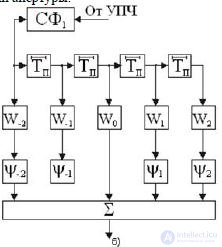
_img_366.jpg) Fig. 17.14 - Functional diagram of the device for optimal signal processing in PCA
Fig. 17.14 - Functional diagram of the device for optimal signal processing in PCA
This device consists of an SF filter matched with a single pulse, a signal storage device for N repetition periods, weight amplifiers with Wi amplifiers of phase shifters φ, and a signal adder.

Comments
To leave a comment
Microwave Devices and Antennas
Terms: Microwave Devices and Antennas