Lecture
In the microwave range, antennas excited by surface waves are widely used. Dignity of the antenna surface waves (AR) is their range, simple design, small sizes.
Good aerodynamic qualities of surface wave antennas allow them to be used as low-protruding antennas for moving objects. Antenna surface of the surface consists of two parts: the causative agent of electromagnetic waves of the radiating part. The radiating part of the antenna is a decelerating structure, which contributes to increasing the directivity of the radiation. Depending on the type of guide part, there are flat, rod-shaped and antenna antennas of surface waves.
The most widespread rod AR, the radiating part of which is made from the dielectric or in the form of metal rods with a dielectric shell.
For example, in fig. 11.1, and the dielectric rod is excited by the open end of the waveguide or a vibrator (Fig. 11.1, b). In this case, a decrease in the deceleration of the wave to the endudielectric rod leads to a better matching of the wave at its output with the free space.
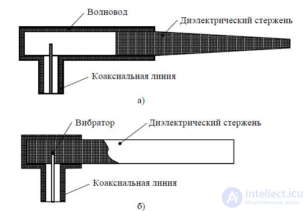
Fig. 11.1 —Dielectric rod antennas with excitation by the open end of a waveguide (a) and with excitation by a vibrator (b)
The disadvantage of dielectric rod antennas is a relatively large mass, which does not allow them to be used on waves longer than (0.2 ... 0.3) m. The presence of losses in the dielectric reduces the antenna efficiency to 70 ... 80% and limits the possibility of their use as transmitting.
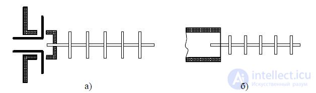
These drawbacks are devoid of a ribbed antenna, which is a metal analog of a dielectric antenna. Ribbed-rod antenna is made of metal disks mounted on a metal rod, excited by a symmetric vibrator (Fig. 11.2, a) or the open end of the waveguide (Fig. 11.2, b) of circular or rectangular cross section. If the discs are made in the form of ellipses and increase their eccentricity, then you can gradually move to the director antenna, which can also be considered as antenna-surface waves. The class of surface wave antennas also includes a spiral antenna.
a) b)
Figure 11.2 - Ribbed-rod antennas with excitation by a symmetric vibrator (a) and with excitation by the open end of a waveguide (b)
If perforated or mesh discs are used, the antenna can be used on meter and longer waves. On meter waves, the advantage of ribbed rod antennas is the comparative simplicity of the design with a rather significant (for these waves) directivity and broadband. On centimeter waves, rod antennas have much smaller dimensions than, for example, horn. It is most expedient to use single rods to obtain radiation patterns with a width of up to 20 ... 30 °. Narrower DND can be obtained using in-phase gratings of rod radiators. A four-rod antenna, for example, has a horizontal radiation pattern of 10 °. Vibrator antenna the same NW would provide only with the number of vibrators equal to 10 ... 12.
Along with dielectric rod and ribbed-rod antennas, plane dielectric and ribbed ARs are often used. Planar dielectric antenna consists of a pathogen in the form of a horn or the open end of a waveguide and a slow-wave system (guide) in the form of a flat metal screen covered with a thin dielectric layer. A surface wave can also be obtained using a metal ribbed system. A flat ribbed antenna consists of a pathogen (for example, a pyramidal horn) of an slow-moving guide system in the form of a metal comb, near the surface of which a surface wave is formed. For flat AR, some deviation of the maximum radiation from the antenna plane is characteristic. This is due to the fact that the metal screen on which the antenna is located has finite dimensions. The antennas of surface waves of a omnidirectional beam in a horizontal plane are made in the form of horizontally arranged dielectric or metal disks with a concentric ribbed structure. The antenna is excited by a vertical vibrator mounted in the center of the disk. The thickness of the dielectric or the height of the ribs on the edge of the disk is reduced to zero in order to align the antenna with the free space. Due to the finite screen dimensions in disk antennas, the maximum of the DN is inclined from the antenna plane. A surface wave arises at the interfaces of a medium with different electrical parameters, the phase velocity in one of which is less than in the second. One of these environments in the antenna technology is air, and the other can be a medium in which “slow” waves propagate, having a speed less than the speed c. A surface wave is formed in an optically less dense medium, is guided by the surface of a section of media with different parameters and propagates along this surface, as if pressed against it. In this case, the amplitude of the electric field strength along the surface almost does not attenuate. And in the air, the amplitude of the field strength decreases exponentially in the direction normal to the interface. All energy is transferred by a wave in a thin layer adjacent to the guide surface. In an optically more dense medium, as a result of the superposition of the incident and reflected waves in the direction of the internal normal to the interface, a standing wave is established (Figure 11.3).
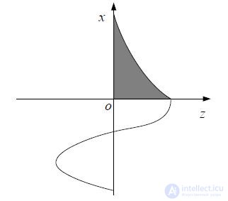
Figure 11.3 - The distribution of the amplitude of the surface wave field
The surface wave propagates in the direction of the z axis, the phase velocity V f this
waves less than the speed of light in an optically less dense medium and are within
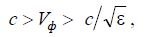
where c is the speed of light in the air; - relative dielectric constant of a more dense medium; - the speed of light in a more dense environment.
Antenna technology uses surface waves propagating along a flat and circular cylindrical interface. Surface waves are formed both near the flat interface between dielectrics, and near the surface of dielectric rods, near wires with loss or covered with a dielectric layer, as well as metal-like combed or corrugated surfaces. The thickness of the air layer in which the main part of the surface wave energy is distributed depends on the deceleration coefficient с _img_222.jpg) V f . The greater the deceleration rate,
V f . The greater the deceleration rate,
the more concentrated the surface wave is near the slow-wave structure.
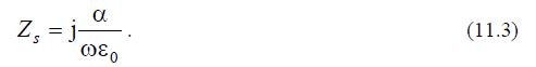
The guide surface, near which a surface wave is created, is usually characterized by surface resistance (surface impedance) equal to the ratio of the electric and magnetic tangents to the slowing surface at the dielectric-air interface.
For an electric-type wave (Hz = 0), the surface impedance of the antenna is defined as the ratio of the longitudinal component of the electric field strength, the tangent delayed surface, to the transverse component of the magnetic field strength.
With a flat interface, the surface impedance of the antenna can be determined by the formula

Representing the component of the magnetic field in the form
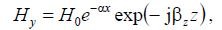
From the Maxwell equations, it is possible to determine the components of the electric field:
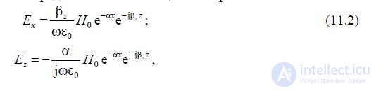
where is the attenuation coefficient of the surface wave field in the direction of the x axis; z is the coefficient of the surface-wave in the longitudinal direction.
The coefficients and z in (11.2) are related by 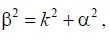 where
where 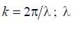 working wavelength range.
Substituting Ez and Hy in (11.1), the surface impedance is obtained as
Thus, the condition for the existence of a surface wave is the inductive nature of the surface impedance. In real conditions, choose a surface in which the reactive part of the surface resistance is much higher than the active. The requirement of reactive surface resistance is dictated by the following considerations. ARCs are traveling wave antennas that have a maximum gain if c / V f > 1, i.e., when V f f will be less than the speed of light with a reactive surface impedance.
To get an idea of the radiation mechanism and methods of calculating AR, we consider two models: a flat system, limited in the direction of wave propagation, and a cylindrical system (Fig. 11.4).
Let the flat system be not limited in the x-axis direction, then in systems using a horn radiator, a surface wave is excited, propagating in the z-axis direction. Since the surface structure is bounded in the z direction and at the end has non-uniformity, the requirement to fulfill the continuity conditions of an electromagnetic polarity causes the appearance of wave types causing energy emission. In this case, there is such a character of radiation as when creating equivalent currents of an unperturbed surface wave on the radiator near the inhomogeneity site.

Figure 11.4 - Surface wave antenna models: a) model of a flat system; b) cylindrical model
Two approximate methods are mainly used for the calculation of the AR radiation field.
Equivalent disclosure method. The basis of this method is the assumption that radiation occurs only in places of heterogeneity of the surface structure. In a simple-rod emitter, heterogeneity occurs at its end, as in a conical horn. As in the case of a horn radiator, when the distribution of the field arising in locohomogeneity (in the mouth of a horn) is taken as the distribution of radiation sources (without taking into account the reflection coefficient), the perturbed distribution of the field in the transverse plane at the rod end is taken as the basis for calculating the radiation of a rod. This transverse plane for a rod radiator is equivalent to the opening. Contrary to the open mouth of the horn radiator, the equivalent opening of the surface wave antenna is infinite, but since the field amplitudes rapidly decrease with increasing distance from the antenna axis, almost all of the radiation occurs through the limited opening. Thus, it is believed that the radiated electromagnetic field is created by an in-phase-excited surface, which is part of the flat front of the surface wave, radiated by the end of the antenna perpendicular to its axis. The amplitude of the exciting field is distributed on this surface by an exponential law. The greater the deceleration factor c / V f , the smaller the effective radiating surface.
The radiation maximum is directed perpendicular to the wave front, i.e. along the antenna axis. The deceleration factor and the dimensions of the radiating surface are determined based on the structure of the field of the infinite slowing structure, and the field distribution in the equivalent aperture corresponds to the normal unperturbed field distribution in the cross section. The finite length of the decelerating structure value c / V f not
constant along the length of the antenna, which leads to errors when calculating the DN. The accuracy of the calculation is increased by increasing the length of the antenna.
The second method is based on the representation of a decelerating structure in the form of a traveling-wave antenna with a slow phase velocity. In this case, the antenna is a combination of continuously located elementary emitters. In this case, the wave reflected from the end of the antenna is neglected. The radiation emitted by the ARF field is the result of the interference of the field emitted by the retarding structure and the field directly emitted by the pathogen that did not enter the surface wave. Direct radiation of the causative agent distorts the DNF.
With short emitters, it is advisable to use the second method.
Among various microwave antennas, dielectric antennas occupy a separate place in a certain sense. The simplicity of the design and the good aerodynamic qualities cause their quite frequent use, especially in aircraft radio equipment.
A dielectric antenna consists of an electromagnetic field pathogen and the antenna itself (guide system). The guiding system for the surface wave is a dielectric rod. The causative agent is an electric vibrator, which is the end of the internal wire of a coaxial cable, a metallic round or rectangular waveguide (see fig. 11.1). Dielectric rods are made of high-frequency dielectrics with low losses (polystyrene, lucite, fluoroplastic, etc.). Antenna technology uses two types of dielectric rods: solid and hollow. Hollow rods are also called dielectric tubes. Solid rod dielectric antennas can be conical, cylindrical or other shape.
DN of a cylindrical rod antenna has large side lobes (up to 30 ... 40% in power), due to the reflection of the surface wave from the rod end. To reduce the reflection rod is performed in the form of a cone, tapering towards the end. In this case, the deceleration of the wave decreases by the end of the antenna, the propagation phase velocity of which approaches the speed c, and the matching of the antenna with the surrounding space is improved. In this connection, the reflection of the surface wave from the rod end decreases, which leads to a significant decrease in the level of side lobes.
At a dielectric antenna, an electromagnetic field is excited by a source in that part of the dielectric rod, which is covered by a circular metal holder, and then propagated as in a waveguide. Having reached the boundary of the metal holder, the wave continues to propagate through the dielectric rod, simultaneously penetrating through the open part of the surface of the rod into the outer space. To determine the radiation field of a dielectric antenna, you need to know the electromagnetic field inside the rod and outside it. This problem is currently solved for the idealized case of a rod of infinite length and constant round
When determining the radiation field of a dielectric antenna, it is considered that the electromagnetic field inside and outside a rod of finite length has the same structure as in an infinitely long rod. When a dielectric antenna is excited by a vibrator or a circular waveguide with the H11 wave in the rod, with the correct choice of its diameter, the main waveNE11 is excited. The lines of the electric field strength vector E in the cross section of the rod have one preferred direction, perpendicular to the axis of the antenna.
The waves arising in the rod cause polarization of the dielectric along the power lines of the electric field component (in the transverse planes of the rod), i.e., the polarized electric currents that are mainly transverse in the rod are excited. These currents (displacement currents) can be considered as emitters with a uniform distribution of amplitudes in the direction of the antenna axis or a linear distribution of phases. Thus, a dielectric rod antenna can be considered as a traveling-wave antenna of axial radiation with a slow phase velocity. Therefore, the DN of the dielectric antenna in the E and H planes is calculated using the formulas:
- in plane E 
- in the H plane

The factor F 1 (θ) is a function of the directivity of the traveling-wave ruler and is determined by the formula
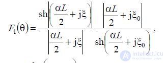
Where  - attenuation coefficient, which
determined experimentally.
When calculating the antenna DN of polystyrene, lusite and other dielectrics with relative dielectric constant e = 2.5 ... 2.6, it can be assumed that: 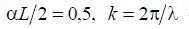 —Wave number, is the angle between the axis of the antenna and the direction to
point of observation, c / V f - coefficient of wave slowdown in a dielectric waveguide.
In fig. 11.9 shows the dependences of F 1 (θ) on for various values of L _img_233.jpg) 2. The figure shows that the more чемL
2. The figure shows that the more чемL _img_234.jpg) 2 (чем быстрее убывает амплитуда поля от начала антенны к ееконцу), тем шире главный лепесток ДН и больше боковые лепестки. Основная особенность ДН при >0 заключается в отсутствии нулевых значений поля, т. е. в слиянии главного и боковыхлепестков в кривую со слабо выраженными экстремумами. Чем больше , тем слабее выражены экстремальные точки.
2 (чем быстрее убывает амплитуда поля от начала антенны к ееконцу), тем шире главный лепесток ДН и больше боковые лепестки. Основная особенность ДН при >0 заключается в отсутствии нулевых значений поля, т. е. в слиянии главного и боковыхлепестков в кривую со слабо выраженными экстремумами. Чем больше , тем слабее выражены экстремальные точки.
На рисунке 11.10 показаны, в качестве примера, зависимости F 1 ( θ) от для различных значений параметра L _img_235.jpg) 2. Множитель F 1 ( θ) оказывает определяющее влияние на ДН.
2. Множитель F 1 ( θ) оказывает определяющее влияние на ДН.
Полагая, что затухания в стержне пренебрежимо малы, F получается
для F 1 ( θ) выражение
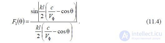

Рисунок 11.9 — Зависимости множителя F1 , входящего в выражение для диаграммы
направленности диэлектрической антенны, от параметра a
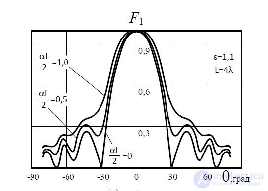
Рисунок 11.10 — Зависимость F 1 (Q) от Q при различных значениях параметра L/2
Множитель F 2 (Q) характеризует влияние на ДН поперечного размера стержня, т. е. определяет направленность элементарного объемного участка, имеющего форму плоскогопоперечного слоя круглого сечения. ДН элемента длины стержня круглого сечения определяется по формуле

где Л 1 — лямбда-функция первого порядка; d — средний диаметр диэлектрического стержня.
Наличие множителя F 2 ( θ) приводит к тому,
что ДН стержневых антенн более направлены, чем плоскостных. Однако множитель F 2 ( θ)заметно влияет на ДН антенны лишь при коротких стержняхбольшого диаметра (порядка и более).
Множитель 
характеризует влияние на ДН одиночного элемента тока (относится только к плоскости Е) и в пределах θ=0…45 0 слабо изменяется.
Более быстрое убывание функции F 3 ( θ) с увеличением угла θ начинается при углах θ 45 . Таким образом, наличие множителя F 3 ( θ) мало сказывается на форме основного лепестка ДН антенны. Основное отличие ДН в Е-и Н
плоскостях у диэлектрических антенн заключается в том, что в Н-плоскости боковые лепестки ДН заметно больше. Ширина основного лепестка в обеих плоскостях почти одинакова. ДНдиэлектрических антенн малого диаметра определяется в основном функцией F 1 ( θ) , а большого диаметра — произведением функций F 1 ( θ) и F 2 ( θ).

Comments
To leave a comment
Microwave Devices and Antennas
Terms: Microwave Devices and Antennas