Lecture
An antenna is an integral part of any radio system. The main purpose of the antenna is to radiate and receive electromagnetic energy. The main task that any antenna performs is the conversion of one type of energy into another. The transmitting antenna converts the energy of high-frequency currents into the energy of a spatial electromagnetic wave, solving the second task - a certain radiation directivity is created, i.e. concentration of the electromagnetic field in a certain direction. The receiving antenna solves the reciprocal problem — it converts an electromagnetic wave into an electric current, coming within a certain sector of the corners of space.
The diversity of antennas is determined not only by the design features, but also by their functional purpose. Antennas can be divided into groups according to various criteria. In terms of electric or magnetic, by type of polarization, to antennas of horizontal, vertical or circular polarization, across the width of the frequency range to narrowband and broadband, to frequency properties to resonant and aperiodic, to the direction of radiation to directional and non-directional.
By the method of excitation and gain of the antenna are divided into four categories:
- simple emitters (Fig.5.1):
a) Hertz vibrator;
b) vibrator;
c) conical vibrator;
d) disconnected antenna;
e) asymmetric vibrator;
e) conical antenna;
g) a cup radiator;
h) loop antenna;
i) loop vibrator;
- group emitters;
- radiating structures;
aperture radiators.
Such a classification is not always unambiguous.
Intersections are often observed between individual categories.

a B C)

d) e) e)

g) h) i) Fig. 5.1 - Simple Emitters
Emitters consist of individual elements.
These include:
- the simplest emitters;
- Antennas: linear, curly.
The simplest emitters include the following structures.
Spherical radiator, also called isotropic antenna. It is a lossless antenna that radiates uniformly in all directions or receives from all directions. The antenna pattern is a sphere. Such an antenna is not feasible, but is used as a theoretical benchmark.
Hertz's dipole. The emitter is named after the German physicist G. R. Hertz (1857-1894); it is also called the elementary electric radiator or the elementary electric vibrator. To realize the dipole, a vibrator with end capacitors is used, shortened relative to the radiation wavelength. Compared with an isotropic radiator, it has a direction perpendicular to the axis of the vibrator. The radiation pattern has the form of two circles with zero values in the directions of the dipole axis.
Dipole Fitzgerald. Named after the Irish physicist F. J. Fitzgerald
(FG Fitzerald) and is also known as an elemental magnetic emitter or an elementary magnetic vibrator. It is implemented in the form of a current frame, the size of which is less than the wavelength. The difference from an isotropic radiator is characterized by a directivity corresponding to the frame plane. The directivity pattern consists of two circles with two zero values in directions perpendicular to the plane of the frame.
Huygens emitter. It bears the name of the Dutch physicist X. Huygens (Ch.Huygens); It is a combination of a small frame (magnetic part) and a short vibrator in its plane (electrical part). Such a device is used to determine the direction of the direction finding. Directional patterns in the horizontal and vertical planes look like cardioids and have one zero point.
Linear antennas. These include the following structures.
Dipole, or vibrator. The simplest antenna with symmetrical power is a two-port (dipole) with sinusoidal current distribution. A half-wave vibrator is characterized by a length of λ / 2 (the old name is a doublet). The length of the wave vibrator is equal to λ (double "Zeppelin"). An antenna with a length of 1.28λ is called an elongated double “Zeppelin”. A wideband vibrator is a dipole in the form of a cone (conical vibrator, double conical vibrator) or a planar dipole (fan-shaped vibrator, flat vibrator). Knesymmetric (mostly vertical) vibrators include coaxial vibrator, conical-cylindrical and disconal antennas.
Asymmetrical vibrator (monopole). Other names are unipol, half-dipole, Marconi antenna. The simplest type of antenna with asymmetrical power belongs to a single-pole (monopole) or half-dipole with a sinusoidal current distribution over a conductive surface (ground). The antenna length is λ / 4. Such antennas belong to the Groundplane type if the conducting surface is replaced by a counterweight. Vertical antennas of length λ / 2 and 5λ / 8 are also used. Broadband monopoles include conical and flat fan antennas.
Long wire. The length of these wire antennas is longer than the working wavelength. They are symmetrical or asymmetrical, they feed on standing or running waves, they can be resonant or aperiodic. Examples are kite and balloon antennas, Beverage antenna, TFD, T2FD.
Frame antennas - closed antennas with elements in the form of frames.
Small frame (magnetic antenna). Its perimeter is small compared with the wavelength and is approximately 1/10 λ. An example of this type of antenna is a coil winding or a ferrite rod antenna.
Large frame. The perimeter of the large frame is approximately 1 λ. Such antennas include loopback vibrator, disk and square antennas and a Delta-Loop antenna.
Slot antennas. Closed antennas with slotted elements on a conductive surface. The length of the slots is from λ / 2 to λ, and they themselves are linear (slots on
plane or cylinder) or cross-shaped (for example, on a disk slot antenna).
Active antennas - are a passive element (vibrator or monopole) with built-in "active part" (amplifier). The result is a compact, sensitive and broadband antenna system, but its linearity is limited and the principle of reciprocity is not observed. Example: active receiving antennas.
Group emitters. The emitter is formed by a group of individual radiating devices. The radiation properties are determined by the location of the emitters and the characteristics of their power in phase and amplitude. Thanks to phase control, electronic scanning of space by the main beam is achieved (phase controlled group). The number of individual emitters can be arbitrary, which allows you to get almost any distribution of radiation in space. This category of antennas is divided into the following groups:
- linear: separate emitters of the group are lined up (one-dimensional construction);
- planar: separate radiators are located in one plane (two-dimensional distribution), as a rule, in front of the reflector; a group may consist of several subgroups (2x2, 4x4, etc.);
- spatial: characterized by three-dimensional placement of single emitters (ring emitters, conformal groups, etc.); -
- with network power, when two power systems are used: matrix, when, when excited at the same frequency, the system allows you to simultaneously form multiple independent radiation patterns (example: Butler's matrix); and adaptive, when the positions of the main beam and zero points of the directivity pattern of the group antenna are achieved by setting the required phases and amplitudes (example: an adaptive antenna system).
The emitters that make up the antennas consist of radiating structures of various shapes. Within the scope of this category, two subspecies of structures are distinguished: - flat; - spatial.
Flat structures include the following (Fig.5.2):
- rectilinear. Individual elements of such emitters are located along a straight line. Example: a log-periodic (LP) vibrator or monopole antenna;
- bent. Example: a log-periodic V-shaped antenna;
- folded. Example: antenna in the form of a meander or zigzag;
- with bends. Example: a log-periodic dipole antenna with a gain optimization circuit (according to Landstorfer);
- twisted (area of spiral antennas). Example: Archimedean spirals, logarithmics, spiral-slot antennas;
- planar. Example: log-periodic planar antenna.
The following are the spatial structures (see fig. 5.2):
-structure with a break. Two log-periodic antennas in contact with the front ends;
- cylindrical helix antennas;
- conical spiral antennas;
Aperture radiators. The emitter is formed by the opening surface (aperture). The directivity pattern of such antennas depends on the shape and size of the aperture and the distribution of the radiation field on it. This category also includes antennas that emit higher harmonics. This category is divided into the following antennas:
-mirror. Also called mirror. The radiation incident on them is reflected without loss;
- horn. The energy that has entered the waveguide is radiated through its open end.
This type includes: a) a hollow conductor antenna. An open hollow conductor of circular or square cross-section acts as an antenna; b) a horn radiator (Fig.5.3). Funnel expansion of the hollow conductor increases its ability to radiation. Examples: E and Η planar sectorial horns, pyramidal and conic rubs;
- lens. Accelerating or retarding lenses are used to transform the curved phase front;
- dielectric. This is a longitudinal radiator, which is based on the conductivity of surface waves.
There are two types:
a) short - the same as the near-field lens;
b) long: rod (for example, polystyrene rod antenna);
tubular (formed by a cylindrical tube);
stepped (made of rods, the thickness of which varies in steps);
lamellar (made up of plates whose thickness varies in steps);
- on scattered waves. The radiation of propagating waves escapes through the holes of the waveguide located at equal or periodically changing intervals. These include: emitting coaxial line; longitudinal slits in the waveguide (Fig. 5.4); transverse slots in a rectangular waveguide; antenna surface waves.
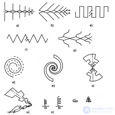
Fig. 5.2 - The structure of the emitters. Antennas: a) log-periodic vibrator; b) log-periodic V-shaped; c) in the form of a meander; d) zigzag; e) log periodic vibrator according to Landstorfer; e) Archimedean spiral; g) logarithmic spiral; h) log-periodic planar; i) log-periodic, contiguous front ends; k) cylindrical spiral; l) conical spiral
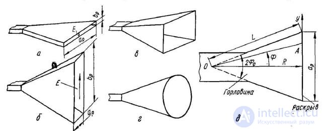
Fig. 5.3 - Horn radiators: a) H- sector; b) E- sector; c) pyramidal; d) conical; e) description of the geometry of the horn
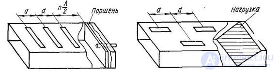
Fig. 5.4 - Wave-slot antenna
3. To determine the radiation power, the Poynting theorem is used.
4. The theory of wire antennas is based on the reciprocity theorem, according to which the theory of receiving antennas is constructed using the results obtained for the transmitting antennas.

Comments
To leave a comment
Microwave Devices and Antennas
Terms: Microwave Devices and Antennas