Lecture
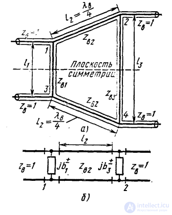
Fig. 3.9. Ring eight-port:
a — general scheme; b — partial two-terminal circuit replacement scheme
Let us find out the possibility of creating directional couplers based on an eight-port network with a plane of symmetry  , made in the form of a closed ring of four segments of transmission lines (for definiteness of coaxial waveguides) with a T-wave (Fig. 3.9, a). Wave resistance
  ,
,  ,
,  and lengths of segments of transmission lines
  and
and  are variable parameters, and the length of the segment chosen equal
  . Four-pole symmetric and antisymmetric excitation have the same equivalent circuit (Fig. 3.9 b), in which the equivalent shunting reactive conductivity
  refer to parallel loops
  and
and  with the conditions of idling (index "+") and short circuit (index "-") and according to the formulas (1.31) are determined by the expressions

 (3.44)
The classical transfer matrices of quadrupoles symmetric and antisymmetric excitation are determined by calculating the product of the three transfer matrices, two of which refer to shunting conductivities  and the third belongs to a quarter-wave transformer with characteristic impedance
  .
.
 (3.45)
Let us consider successively the possibilities of obtaining the directivity of all three types.
1. Type I orientation . Conditions  and
and  , first, mean conductivity equality
  and secondly, lead to a quadratic equation
 (3.46)
with roots  . Equality
  has a consequence [see (3.44)]:
 therefore the length of the transmission line segments and
  should choose
  . Then
  and
and  . According to formulas (3.35) with regard to (3.46), the elements of the ideal scattering matrix of the resulting directional coupler of type I
 ;
;  (3.47)
and equality  , which is a consequence of the unitarity of the scattering matrix (3.33), coincides with equation (3.46). Thus, choosing the appropriate wave impedances and
  , you can set the specified power division at the isolated outputs of the coupler. For example, for equal division of power from input 1 between outputs 2 and 4, one should choose
  and
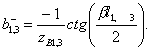
and  . The resulting device with equal power division is called a square (or stub ) bridge . In the frequency band, the matching and isolation properties of the inputs are not saved and the square bridge is characterized by the following parameters:
1) entrance KBV 
2) isolation of inputs 1 and 3, defined as  dB;
dB;
3) the coupling coefficients given by the relations  db
db
The dependencies of these parameters on the frequency are shown in Fig. 3.10, which also shows one of the possible patterns of the printed circuit board, obtained when implementing a square bridge on strip transmission lines.
2. Type II directivity. Conditions  and
and  in the transfer matrix (3.45), first, make
  and secondly, lead to a quadratic equation
 (3.48)
with roots  . Equality
  and
and  can be performed if you choose [see Formulas (3.44)]:
  ;
;  ;
;  that provides
  . According to formulas (3.39) with regard to (3.48), the elements of the ideal scattering matrix of the resulting directional coupler of type II
 (3.49)
and equality  , which is a consequence of the unitarity of the scattering matrix, coincides with equation (3.48) with
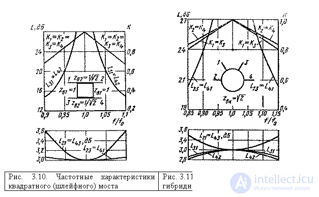
  . The device obtained belongs to the oppositely directed couplers of the common-mode and antiphase type and is specifically called the hybrid ring . Selecting appropriate wave impedances
  and
and  segments of the ring, you can install at its outputs a predetermined division of power. For example, to achieve equal division of power between outputs 2 and 3 when input 1 is excited, the wave resistances of the segments of the ring should be chosen
  . The frequency characteristics of the parameters of a hybrid ring with an equal power division are depicted in Figure 3.11. Where one of the possible printed circuit board patterns is also shown when performing a hybrid ring on stripline transmission lines.
3. Type III directionality. Conditions  and
and  which must be answered by the elements of the transfer matrix (3.45), firstly, it means equality of conductivities
  and secondly, lead to a quadratic equation
 (3.50)
with roots  . Therefore, the minimum length of the segments
  and
and  should be chosen equal
  . In this way,
  . According to formulas (3.43) with regard to (3.50), the elements of the ideal scattering matrix of the resulting directional coupler of type III
 (3.51)
 |
It is easy to make sure that the type III directional directional coupler exactly corresponds to the type I directional coupler, but with replacement  and renumbering inputs. Thus, the implementation of type III directivity in this case does not lead to a new coupler scheme (see Fig. 3.8 and explanations for it in the text).
So, research of the octopolar device shown in fig. 3.9, allows to explain the principle of operation of the widespread enlarged basic elements - the square bridge and the hybrid ring from a unified position. Similar elements can be performed on many types of transmission lines, including rectangular waveguides. In the latter case, not parallel, but serial connection of output waveguides to a closed waveguide ring (i.e. in the E-plane) is used more often. This forces the partial circuits of the two-port networks to change in fig. 3.9, б by replacing parallel loop reactivities  on sequential reactivity
  . Reception of calculated ratios for ring directional couplers of various types with series connection of output waveguides to the ring is recommended for readers as an exercise.

Comments
To leave a comment
Microwave Devices and Antennas
Terms: Microwave Devices and Antennas