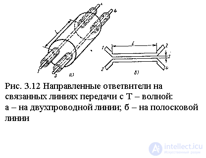
The most compact and wideband directional couplers in the microwave range are obtained by using mutual coupling effects in multi-wire transmission lines with T-waves. In fig. Figure 3.12 shows sketches of two taps of this type.
It is convenient to carry out the analysis of couplers on connected transmission lines by the method of symmetric and antisymmetric excitation using the longitudinal symmetry plane located between the primary 1-2 and secondary 3-4 transmission lines. The partial quadrupoles of symmetric and antisymmetric excitation take the form of segments of a regular transmission line with a T-wave, and the lengths of these segments l coincide with the length of the communication section, and the wave resistances  depend on what boundary condition (Ht = 0 or Еt = 0) takes place in the plane of symmetry of the coupler.
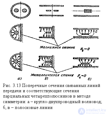
The configurations of the cross sections and the structure of the transverse electric field in the partial quadrupoles of symmetric and antisymmetric excitation for the three types of related transmission lines are shown in Fig. 3.13. From a comparison of the structures of the electric field, it follows that the linear capacitance of the transmission line in the symmetric excitation mode (the boundary condition Ht = 0) must be less than the linear capacitance in the antisymmetric excitation mode (the boundary condition Et = 0), and, therefore, the wave resistances  and
and  in partial quadrupoles satisfy the inequality
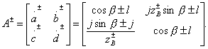
  . Assuming that the input transmission lines of the coupler have a single normalized characteristic impedance, based on the formula (3.20), we can write down the classical transfer matrices of partial quadrupoles as follows:
With this type of transfer matrix of partial quadrupoles it is possible to implement only type II directivity with conditions on matrix elements.  of the form (3.38). According to these conditions, the equality of elements
  provided with the same phase coefficients
  in partial quadrupoles, and the equality of elements
  will take place with a special selection of wave resistances:
 (3.52)
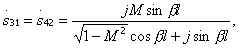
It is significant that the conditions for the implementation of directivity turned out to be independent of the electrical length of the communication section.  , and, therefore, the ideal isolation and full coordination of inputs will be provided at any frequency. The frequency will depend only on the distribution of power at the outputs of the coupler. Using formulas (3.37) and the rules of transition from the transfer matrix to the scattering matrix (see Table 3.1), after simple identical transformations, taking into account the condition (3.52), we get:
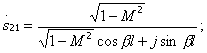
 (3.53)
Where  auxiliary parameter that makes sense of the modulus of reflection coefficient from the junction of transmission lines with wave impedances
  and
and  . From the formula (3.53) it follows that if the length of the communication section
 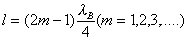 then the transfer coefficient
  maximum and equal to the parameter M. If the length of the communication section is a multiple of the half-wave, then
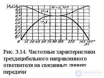
  and all power from input 1 goes to input 2. In fig. 3.14 shows the change of modules
  and
and  in directional coupler on connected transmission lines depending on electrical length
  at parameter
  .
.
A directional coupler on connected transmission lines has two planes of symmetry, and therefore it refers to quadrature directional couplers, i.e. 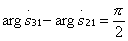
The most commonly used directional couplers on strip and microstrip lines. When designing such taps with given transfer ratios  and
and  satisfying the condition
  , the length of the communication section l can be chosen arbitrarily (most often
  ), then on the basis of formulas (3.53) find the parameter M and determine the values of wave resistance
  and
and  . These resistances calculate the required dimensions of the strip conductors in the cross section of the coupler and determine the required gap between them. At this stage, the calculation has to refer to or reference materials on wave resistance
  and
and  associated transmission lines, or use special computer programs compiled for the selected cross-section geometry of the associated transmission lines. The most difficult is the implementation of directional couplers with a strong bond (M> 0.3), since in this case an extremely small gap between the conductors is usually required (see Fig. 3.12) and technological difficulties arise in ensuring its stability in the production process. When creating directional couplers on coupled asymmetrical microstrip transmission lines, there is another difficulty associated with some differences in phase coefficients.
  and
and  for waves of symmetric and antisymmetric excitation within the communication area. The necessary alignment of these speeds can be achieved by applying an additional dielectric layer to the connected conductors or by adding compensating reactive elements at the ends of the communication section.

Comments
To leave a comment
Microwave Devices and Antennas
Terms: Microwave Devices and Antennas