In amateur practice, antennas are extremely rarely used, the input resistance of which is equal to the feeder impedance of the feeder, and in turn, the output impedance of the transmitter (ideal matching option). Most often there is no such correspondence and it is necessary to use special matching devices. Antenna, feeder and transmitter output should be considered as a single system in which energy transfer should be carried out without loss.
The implementation of this difficult task will require coordination in two places: at the point where the antenna connects to the feeder and the feeder to the transmitter output. Various kinds of transforming devices are most popular: from resonant collective circuits to coaxial transformers in the form of segments of coaxial cable of the required length. All of them are necessary for matching resistance, which ultimately leads to minimization of losses in the transmission line. And, most importantly, to reduce out-of-band emissions.
As a rule, the standard output impedance of modern broadband transmitters (transceivers) is 500m. Most of the coaxial cables used as a feeder also have a standard impedance of 50 or 750m. Depending on the type and design, antennas can have an input impedance in a very wide range of values: from a few Ohms to hundreds of Ohms and more.
It is known that the input impedance of single-element antennas at the resonant frequency is almost active. And the more the transmitter frequency differs from the resonant frequency of the antenna in one direction or the other, the more the reactive component of a capacitive or inductive nature appears in the input impedance of the antenna. In multi-element antennas, the input impedance at the resonant frequency is complex, since passive elements contribute to the formation of the reactive component.
In the case when the input impedance of the antenna is of a purely active nature, it is easy to reconcile it with the feeder impedance using any of the suitable transforming devices. At the same time losses are insignificant. But, as soon as a reactive component is formed in the input resistance, the matching becomes more complex, and a more complex matching device is needed that can compensate for unwanted reactivity. And this device must be located at the power point of the antenna. Uncompensated reactivity degrades the CWS in the feeder and increases losses.
An attempt to fully compensate the reactivity at the lower end of the feeder (at the transmitter) is unsuccessful, as it is limited by the parameters of the feeder itself. Resetting the transmitter frequency within narrow areas of the amateur bands does not lead to the appearance of a significant reactive component, therefore in most cases there is no need to compensate for the reactivity. Properly designed multi-element antennas also do not have a large reactive component of the input resistance, and usually its compensation is not required.
On the air there are often disputes about the role and purpose of the antenna matching device (antenna tuner) when coordinating a transmitter with an antenna. Some put high hopes on him, others consider him an unnecessary toy. What actually (in practice) can and what can not help antenna tuner?
First of all, the tuner is a high-frequency impedance transformer that can compensate for the reactivity of a capacitive or inductive nature if necessary.
Consider a simple example:
A split vibrator (dipole), having an active input resistance of about 700 meters at a resonant frequency, is connected by a 75-ohm coaxial cable (feeder) to a transmitter, whose output resistance is 500 meters. The tuner is installed at the transmitter output and in this case acts as a matching node between the feeder and the transmitter, with which it can easily cope.
If the transmitter is rebuilt to a frequency different from the resonant frequency of the antenna, then reactivity will occur in the input impedance of the antenna, which will immediately appear at the lower end of the feeder. The tuner is also able to compensate for it, and the transmitter will again be matched with the antenna feeder.
What will be at the output of the feeder, at the point of its connection with the antenna?
Using the tuner only at the transmitter output, full compensation cannot be ensured, and losses will occur in the feeder due to inaccurate coordination with the antenna. In this case, you will need another tuner, which will have to be connected between the feeder and the antenna, then it will correct the situation and compensate for reactivity. In this example, the feeder plays the role of a consistent transmission line of arbitrary length.
One more example:
A loop antenna with an active input impedance of approximately 1100 m must be matched to a 50 ohm transmission line. Transmitter output 500m. Here you will need a matching device installed at the point of connection of the device to the antenna. Usually, many amateurs use HF transformers of different types with ferrite cores, but it is more convenient to manufacture a quarter-wave coaxial transformer from a 75-ohm cable.
The length of the cable A / 4 x 0.66, where
I am the wavelength
0.66 is the shortening factor for most of the known coaxial cables.
A coaxial transformer is connected between the antenna input and the 50 ohm feeder.
If it is turned into a bay with a diameter of 15 ... 20 cm, then it will also perform the function of a balancing device. The feeder with the transmitter will be matched automatically, with equal resistance. In this case, the services of the antenna tuner can be waived altogether.
For this example, another way of negotiation is possible:
With the help of half-wave or a half-wavelength coaxial cable in general with any characteristic impedance (also taking into account the shortening factor). It is switched on between the antenna and the tuner located near the transmitter. The input impedance of the antenna about 110 Ohm is transferred to the lower end of the cable and is transformed into a resistance of 500 m using a tuner. In this case, there is a full coordination of the antenna with the transmitter, and the feeder performs the function of a repeater.
In more complex cases, when the input impedance of the antenna does not correspond to the impedance of the feeder, and the impedance of the feeder does not correspond to the output impedance of the transmitter, two matching devices are needed. One at the top for matching the antenna with the feeder, the other at the bottom for matching the feeder with the transmitter. And it is not possible to get by with only one antenna feeder for matching the whole circuit: antenna - feeder - transmitter.
The presence of reactivity further complicates the situation. Antenna tuner in this case will significantly improve the coordination of the transmitter with the feeder, thereby facilitating the work of the final stage, but no more. Due to the mismatch of the feeder with the antenna, there will be losses, and the efficiency of the antenna itself will be reduced. The included SWR meter between the transmitter and the tuner will fix SWR = 1, and this will not happen between the tuner and the feeder due to a mismatch of the feeder with the antenna.
This suggests a fairly fair conclusion: the tuner is useful in that it supports the normal mode of the transmitter when operating on an unmatched load, but it is not able to improve the efficiency of the antenna when it mismatches the feeder.
The P-loop used in the output stage of the transmitter can also serve as an antenna tuner, but under the condition that the inductance and both capacitances change rapidly.
As a rule, antenna tuners, both manual and automatic, are resonant loop tunable devices. Manual have two or three regulatory elements and are not operational in the work. Automatic - roads, and to work at high power - very expensive.
Let's look at a fairly simple broadband matching device (tuner) in Figure 1, which satisfies most variations when matching a transmitter with an antenna. :
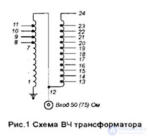
It is very effective when working with antennas (frames, dipoles) used on harmonics, when the feeder is a half-wave repeater. In this case, the input impedance of the antenna at different ranges is different, but with the help of a matching device it is easily coordinated with the transmitter. The proposed tuner can operate at transmitter powers up to 1.5 kW in the frequency range from 1.5 to 30 MHz.
The main elements of the tuner are the HF autotransformer on the ferrite ring from the deflecting system of the TV CNT-35 and the switch to 17 positions. It is possible to use conical rings from TVs UNT-47/59 or others.
The winding contains 12 turns, wound in two wires. The beginning of one winding is connected to the end of the other. Numbering of turns in the table and on the diagram. The wire itself is stranded in fluoroplastic insulation. Wire diameter 2.5mm insulation. Bends are made from each turn, starting from the eighth from the grounded end.
Switch - ceramic, galetny type on 17 positions.
The autotransformer is located as close as possible to the switch, and the connecting conductors between them must be of a minimum length. It is possible to use a switch with 11 positions while maintaining the design of a transformer with a smaller number of taps, for example, from 10 to 20 turns. But in this case, the range of resistance transformations will also decrease.
Knowing the input impedance of the antenna, you can use such a transformer to match the antenna with a feeder 50 or 750m, making only the necessary taps. In this case, it is placed in a moisture-proof box, embedded in paraffin and installed at the antenna's power point.
Also, this matching device can be made as an independent structure or be part of the antenna-switching unit of the radio station.
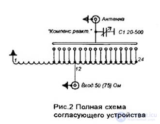
For clarity, the label on the switch handle (on the front panel) indicates the resistance value corresponding to this position. To compensate for the reactive component of the inductive nature, it is possible to connect a variable capacitor C1, Fig.2.
The dependence of resistance on the number of turns is given in Table 1. The calculation was made on the basis of the ratio of resistance, which is in quadratic dependence on the number of turns.
Table 1.

Reconcile with multiple reactivities. The use of one mobile reactivity according to the Tatarinov method is most conveniently carried out in open two-wire transmission lines, where there is easy access to the line conductors and, therefore, it is possible to use short-circuited (or open) moving loops with adjustable length. In closed transmission lines, mobile loops are structurally inconvenient. Therefore, in 1940, V. V. Tatarinov proposed schemes for narrow-band matching with two or three reactivities. In these schemes, the position of the reactivities

|
Fig. 1.14. Matching schemes with two (a) and three (b) fixed parallel reactivity |
Fig. 1.15. To the calculation of the matching scheme using two fixed reactivity |
strictly fixed and controlled degrees of freedom are the magnitudes of reactivity.
The matching scheme with two parallel reactivities is shown in Fig. 1.14, a. In principle, a fixed distance  between reactivity can be any, but not too close to
  where
where  - wavelength in the transmission line, n = 1, 2, 3 ... To increase the range of values of the conductances of loads
  for which agreement can be achieved, distance
  it is desirable to choose equal
  or
or  . The idea of adjusting the matching device is that, by changing the value of the first reactivity
  , thereby regulating the equivalent normalized conductivity at the point of inclusion of the second reactivity until its real part becomes equal to unity. Compensation of the remaining reactive conductivity is done by adjusting the value
  , as well as in the usual way Tatarinov
In fig. 1.15 shows the sequence of calculation matching using a circular nomogram, which is previously supplemented by a circle g = 1, shifted from its normal position to a distance  in the direction of the load (this circle is depicted by a dot-dash, and for concreteness it is assumed that
  . Load conductivity is applied to the nomogram
  me (point 1). Then this conductivity around the circumference of the permanent QBV CL is moved to point 2, which is at a distance of
  from the load. Then you should move from point 2 along the corresponding circle g = const to point 3, which corresponds to the connection of reactive conductivity
  . Point 3 after transformation through a length of line segment
  (which is equivalent to moving around the circumference of a permanent IPM at an angle
  towards the generator) necessarily falls on the line g = 1 at point 4. Connecting the second reactive conductivity
  moves point 4 to the center of the nomogram 5 in provides final agreement. Instead of point 3, a more distant point 6 on the dash-dotted circle could be used. However, this will require a large amount of conductivity.
  , IPM in the area between conductance
  and
and  decrease, respectively, the value should increase
  . Under these conditions, much more electromagnetic energy will be stored in the matching device, and the matching network together with the load forms a resonant system with a higher quality factor (and consequently, with a smaller matching frequency band) than when using point 3.
With an arbitrary load using one fixed-in-position reactivity in the transmission line, it is not always possible to fulfill the first matching condition, i.e. provide g = 1 at the location of the second reactivity. Therefore, they often resort to a matching device with three reactivities (see Fig. 1.14, b). Depending on the active conductivity of the load in the cross section where reactivity is included, the coordination is carried out either by the first and second reactivity at  <1, or second and third when > 1. Free reactivity is excluded from the scheme by adjusting B = 0. However, other matching methods are possible, in which adjustments of all three reactivities are used.
From the considered examples, it follows that in a narrow-band matching devices, two adjustable degrees of freedom are in principle sufficient (the switching-on point of the quarter-wave transformer and its characteristic impedance, the reactivity value and the switching-on point, two fixed reactivity, etc.).
In transmission lines with a T-wave, parallel or sequential loops are most often used as concentrated reactivity. In waveguides, they prefer small-sized matching elements - pins and diaphragms.

Comments
To leave a comment
Microwave Devices and Antennas
Terms: Microwave Devices and Antennas