Lecture
Lens antennas. Classification. Features of construction. Main characteristics.
16.1. The principle of operation of lens antennas and the lens profile equation.
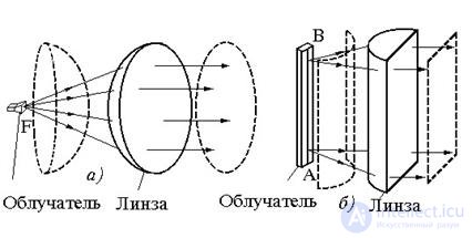
A lens antenna is a combination of an electromagnetic lens and an irradiator (Fig. 16.1). In highly directional lens antennas, the lens serves to convert a spherical (or cylindrical) wave front, incident from a weakly directed irradiator, into a flat front after the lens.
An electromagnetic lens is an environment in which the phase velocity of propagation of electromagnetic waves (υ ф ) differs from the speed of light C. If υ ф f > c, the lens is called accelerating. Attitude
the speed of light to the phase velocity of the wave in the lens is called the refractive index
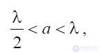
lenses and is denoted by  . The surface of the lens facing the illuminator is called the illuminated side, the opposite (shadow) surface of the lens is called the aperture. There are lenses with a single refractive surface (Fig. 16.2, a, b, c, d), when the transformation of the wave front, incident on the lens from the irradiator, occurs only on the shaded or illuminated surface of the lens and double-surface, in which the focus is polarized as illuminated, and shadow surfaces (Fig. 16.2, d, e). Opening the lens in the general case can be formed by a surface of arbitrary shape. Lenses with flat-opening (Fig. 16.2 a, b) refract the field falling on them on the illuminated surface, lenses with a spherical illuminated surface have a curvilinear shadow refractive surface (Fig. 16.2, c, d). In the future, unless otherwise specified, we will consider single-surface lenses with a flat radiating aperture. The shape of the open lens can be round (in the lenses representing the body of rotation relative to the focal axis, Fig. 16.1, a), or rectangular (in cylindrical lenses, (Fig.16.1, b)).
The illuminated surface of the lens is convex for retarding (Fig.16.2, a) and concave (Fig.16.2, b) for an accelerating lens. This follows from the following discussion.
In a retarding lens, the phase-front alignment occurs due to the slowing down of the movement of certain parts of the front. As follows from fig. 16.2, a, the central parts of the wave front should slow down more than peripheral ones. In the accelerating lens, however, the phase-front is straightened due to the acceleration of the movement of those areas that pass through the lens. Such areas (see Fig. 16.2, b) to a greater extent should be the peripheral parts of the front.
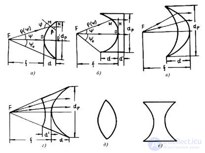
Fig. 16.2 - Types of lenses: a - retarding with illuminated refractive surface; b - accelerating illuminated refractive surface; в - slowing down with a shadow refractive surface; r is the accelerating shadow refractive surface; d, e - two-surface retarding and accelerating lenses.
The irradiator of a spherical lens antenna is positioned so that its phase center coincides with the lens focus F. Under this condition, the spherical wave front emitted by the irradiator proceeds as if from the focus of the lens. In cylindrical lens antennas, the feed is a linear antenna radiating a cylindrical wave. The axis of this cylindrical wave should coincide with the focal line AB of the cylindrical lens (Fig.16.1, b).
The following requirements are applied to a kabluchatel lens antenna:
The irradiator in lens antennas can be used: the open end of the waveguide, a small horn, a vibrator with a reflector, or a number of other weakly directed irradiators that satisfy the above listed requirements.
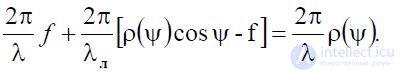
Lens profile equation. The principle of the lens can be explained using the laws of geometric optics: a beam incident on the illuminated surface of the lens with a refractive index n at an angle (phi) is refracted and further propagates at an angle (betta) (fig.16.2, a), determined from the relation:
In order to obtain a sharply directed radiation, the rays diverging from the focus along the radius must be parallel after refraction by the lens. Thus, the lens profile is selected from the conditions so that the spherical wave front emanating from the focus of the lens can be transformed into a flat front after passing the lens. From the standpoint of phase relationships, this means that the electrical path length from the focus of the lens to an arbitrary point N on the aperture must be the same. At the same time in the flat aperture of the lens is formed a phase field.
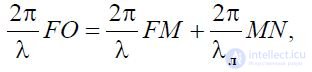
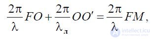
Referring to Figure 16.2, a, b, which show the profiles of the accelerating and slowing lenses and the corresponding notation. Consider two points O and N on the opening of the accelerating lens. Point O lies on the focal axis of the lens, point N is arbitrary. At point O, the wave enters from the focus F in a straight line FO; to point N - by FMN. The condition of equality of the electric lengths FO and FMN is:
 (16.1)
where through  - marked the wavelength in free space;
l is the wavelength in the lens.
We introduce the notation  (f - focal length).
Then  At the same time (16.1) can be written as
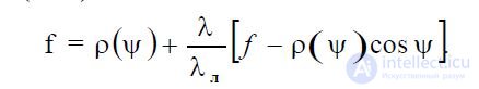
Given that the refractive index: 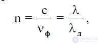 , (16.2)
finally we get:
 . (16.3)
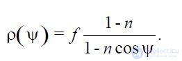
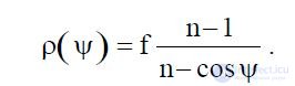
When n <1, equation (16.56) is the equation of an ellipse in the polar coordinate system. It is absolutely analogous for two points O'and N in the aperture of the slowing-down lens, the equality of the electrical path lengths is:
or
Where do we get the following equation for the profile of a slow-motion lens
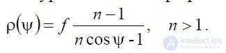 . (16.4)
Equation (16.4), is the hyperbola equation in the polar coordinate system. For single-surface lenses, the illuminated spherical surface (for axisymmetric lenses) (Fig. 16.2, c) or the circular cylindrical surface (for cylindrical lenses) (Fig. 16.2, d) the equalization of the profile of the shadow surface has the following form: n1
 (16.5)
For n> 1, equation (16.5) is the equation of an ellipse, and for n <1, it is a hyperbola equation. Slow-down lenses are made of low loss dielectric.
The refractive index of such lenses is completely determined by the relative dielectric.
permeability of the lens material єd and equal to  Since практическиd practically does not depend on frequency in a very wide frequency range, as follows from equation (16.3), the profile of the slowing down lens does not depend on frequency and, therefore, dielectric lens antennas belong to the class of broadband sharply directional antennas. Their band is limited by the operating band frequency of the irradiator.
Accelerating lenses are a set of thin metal plates (Fig. 16.3), arranged parallel to the electric field vector E, falling from the irradiator.
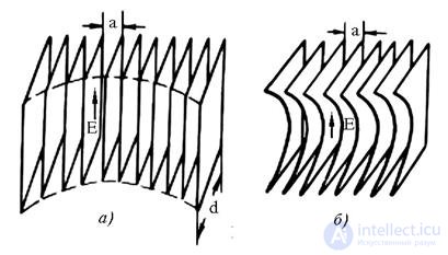
Fig. 16.3 - Metal plate accelerating lenses: a - with H - sectorial horn;
b - with E - sectorial horn.
The space between the plates forms a flat waveguide. If the width of this waveguide a is selected from the condition:
 , (16.6)
then a wave of type H10 can propagate in a flat waveguide, and all other waves are in a critical mode. Phase wave velocity
H 10 equals: 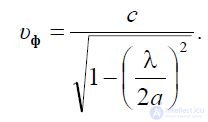
therefore, the refractive index of the metal plate lens is determined by
by ratio
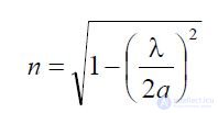 (16.7)
Inequality (16.6) imposes the following theoretical constraint on the range of refractive index selection: 0
Metal plate lenses are most often used in combination with horn antennas to compensate for phase errors in the aperture of a horn. In the H-sectorial horn, a lens of rectangular plates of equal thickness d is used. The ends of the plates inside the horn are located on the surface of the elliptical cylinder (Fig. 16.3, a). In E sectorial lenses, a lens made of identical plates profiled by an ellipse is used (Fig. 16.3, b). To align the phase front in the pyramidal horn, the lens is assembled from profiled plates of different thickness that focus simultaneously on the E and H planes.
The choice of focal length and thickness of the lens. Zoning lenses. The lens thickness d (Fig. 16.2, a, b) depends on the focal length f and the aperture width dр. Using the expression (16.4) for a retarding lens, we obtain:
 (16.8)
Accordingly, using (16.3), for an accelerating lens, we have:
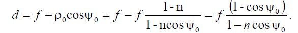 . (16.9)
Substituting in (16.61) and (16.62) the cosine expression of the aperture angle of the lens through the aperture width
2 after simple transformations, we obtain the following expressions for the thickness of the lens: d p 2 2

for retarding lens 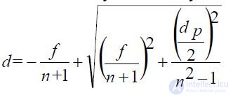 (16.10)
for accelerating lens 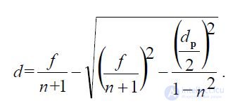 . (16.11)
From relations (16.10) and (16.11) it follows that for a slowing-down lens d> 0 for any parameters n> 1, d p and f; for an accelerating lens d <0, only under the condition:
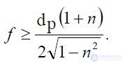 . (December 16)
This means that the retarding length can be constructed at any ratios between n, d p and f; the accelerating lens cannot have focal length
less than the right side of the expression (16.12).
It can be shown quite analogously that for single-surface lenses with a shadow refracting surface the thickness of the lens is determined as follows:
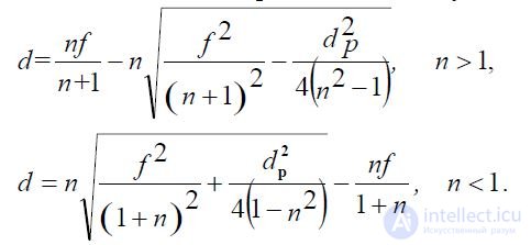
(16.13)
When n> 1, i.e. for a retarding lens with a shadow refractive surface, there is a restriction (16.12) on the relationship between the parameters of the lens.
Note that the actual thickness of the accelerating lenses is always greater than the thickness d, defined by the relations (16.11), (16.13), by the design thickness d (Fig. 16.2, b, d).
In fig. 16.4 shows the graphs of the relative thickness of a lens with a flat aperture on the refractive index, constructed from relations (16.10), (16.11). From these graphs it can be seen that for a given opening width, the lens thickness is smaller, the longer the focal length and the greater the refractive index differs from 1.
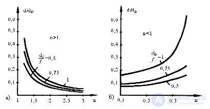 Fig. 16.4 - Dependence of the relative thickness d / d p of the retarding (a)
and accelerating (b) lenses from the refractive index n
The increase in focal length is associated with an increase in the longitudinal size of the antenna, and the more dramatic difference in the refractive index from 1 leads to an increase in the reflection of energy from the lens surface. Therefore, in practice, taking into account the interrelation of parameters, the refractive index is chosen in the interval n = (1.3 ... 1.6) for slowing down and in the interval n = (0.5 ... 0.7) for accelerating lenses, and the focal length is chosen approximately equal to the width of the aperture of the lens (f is approximately equal to d p ). The thickness
the lenses are several tens of percent of the aperture width, and the accelerating lenses are much thicker than the retarding ones. To reduce the thickness of the lens, a special method called lens zoning is used. Its essence lies in the fact that the illuminated part of the lens is stepped (Fig. 16.5). The surface of the lens between the adjacent steps is called the zone. The depth of the steps t is chosen such that the electrical lengths of the path from the focus of the lens to two arbitrary points in the aperture of the lens, characterized by the fact that the rays enter them, passing through the adjacent zones, differed by 2 n radians. At the same time, the field in phase in the lens aperture is not disturbed.
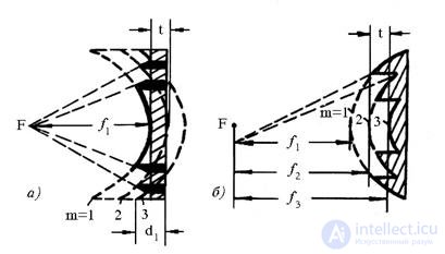
Fig. 16.5 - Zoned accelerating (a) and slowing (b) lenses
The equation of the surface of each m-th zone can be written in the form (16.3) or (16.4) with the only difference that the focal distance fm for each m-zone is chosen 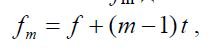 , (16.14)
Where  , (16.15)
moreover, the sign "+" is taken when n <1, and the sign "-" when n> 1. Zoning leads, along with the positive effect of reducing the thickness of the lens d1, and to a number of negative effects. First, in non-irradiated areas appear in zoned lenses (hatched in Fig. 16.5, a), in which the wave slides along the step, or out-of-phase portions in the angular sector shown by dotted lines in Fig. 16.5, b. This leads to a certain decrease in the coefficient of directional action (KND) of lens antennas and to an increase in the level of side lobes. Secondly, the depth of the step, as it follows from (16.15), depends on the wavelength. Therefore, zoning in dielectric lenses leads to a decrease in the relative operating frequency band.
 to the value of
 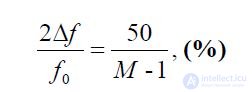 (16.16)
where M is the number of zones; f0 is the average frequency; 2 delta f is the absolute frequency band.
Accelerating metal plate lenses are fundamentally narrow-band because of the dependence of the refractive index on frequency. So, the working frequency band of these lenses
with permissible phase errors  and when n = 0.5 at the average frequency is equal to
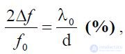 , (16.17)
and in zoned metal plate lenses the working frequency band with the same restrictions is determined by the relation:
(16.18)
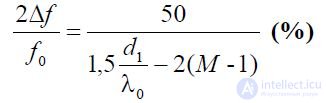
From comparison (16.17) and (16.18), it follows that in metal plate lenses, zoning even allows you to expand the working frequency band.
The directivity pattern of lens antennas. Since the considered lens antennas belong to the class of aperture antennas with a common-mode aperture, to calculate their directional diagrams, it is enough to determine the amplitude distribution of the field in the opening and to calculate the diagonal direction pattern.
The amplitude distribution in the opening of the lens antenna is primarily determined by the shape of the amplitude pattern of the irradiator F region (psi), as well as the properties of the lens, and can be represented as:
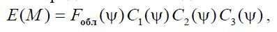
, (16.19)
where M (r, d) or M (x, y) is a point on the aperture of an axisymmetric or cylindrical lens, corresponding to the beam,
falling on the opening of his falling on the illuminated surface of the lens subarm , augol determined by the equation:

for axisymmetric lenses, 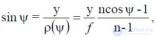 , (16.20)
for cylindrical lenses. Coefficients 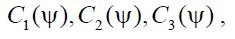 included in the ratio (16.19), must
123 redistribution of power in the aperture of the lens due to refraction, reflection from the surface of the lens and losses in the lens.
To analyze the effect of refraction on the shape of the amplitude distribution, we turn to fig. 16.6, which shows two beams of rays having the same angular sectors. 
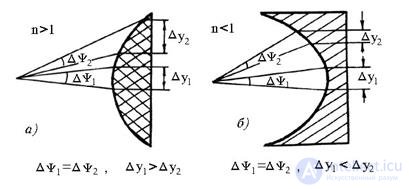
Fig. 16.6 - To the explanation of refraction in slowing (a) and accelerating (b) lenses
With a non-directional irradiator, the same amount of energy from the irradiator will be distributed in these sectors. After refraction by the lens, the energy will be distributed in beams of different sections. This phenomenon is called refraction. For accelerating lenses 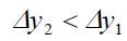 for slowing down
  vice versa. Therefore, due to refraction, the energy flux density and, consequently, the field amplitude in the aperture will increase towards the edges of the accelerating lens and decrease towards the edges of the slowing lens. The quantitative change in the amplitude distribution due to refraction can be calculated from the following relationships:
for a cylindrical lens
for spherical lens
(16.21) 
Figure 16.7 shows the dependences of the coefficients C1 (psi) for spherical (Fig. 16.7, a) and cylindrical (Fig. 16.7, b) accelerating and slowing lenses for different values of refractive coefficients n.
Fig. 16.7 - С 1 ( psi) dependence for axisymmetric (a) and cylindrical (b) lens antennas
The effect of reflection on the amplitude distribution in the aperture will be analyzed using the example of a dielectric lens. The reflection coefficient Γ from the illuminated surface depends on the polarization of the incident field and can be approximately determined by the formulas for the reflection coefficient of the projection of the air-dielectric boundary.
Therefore:
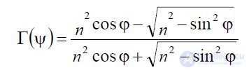
(16.22)
for parallel polarization (the electric field vector E is parallel to the plane of incidence),
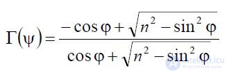
(16.23)
for perpendicular polarization (the electric field vector E is perpendicular to the plane of incidence). In formulas (16.22), (16.23) is the angle of incidence of the wave on the surface of the lens, measured from the normal to the surface at the point of incidence. The reflection coefficient a from the flat shadow surface of the lens does not depend on polarization and is equal to:
(16.24) 
Waves reflected from the illuminated and shadow surfaces of the lens interact weakly with each other, i.e. the energy of the first wave is fairly uniformly dissipated in space, the energy of the second is focused at the focus of the lens, creating additional reflections in the feeder path of the lens feed.
Therefore, the amplitude distribution in the aperture of the lens is influenced mainly by the reflection from the illuminated surface of the lens and the factor C2 (psi ) is approximately equal to:
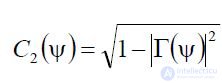 , (16.25)
where Γ (psi), depending on polarization, is calculated according to (16.22) or (16.23).
For perpendicular polarization, C 2 (psi) gives an amplitude distribution that decreases towards the edges of the lens; for parallel polarization, the C 2 (psi) factor first gives an increase in the amplitude distribution as the observation point moves from the center of the flat aperture to the edge, and then decreases.
The C 3 (psi) factor in (16.19) depends on the influence of active losses in the lens on the shape of the amplitude distribution in the aperture. For dielectric lenses, the C 3 (psi) graph has a slightly elevated shape towards the edges, since there is more loss in the center (due to the greater thickness of the lens) than at the edge. Multiplier dependency  for dielectric
lens antennas has the form:
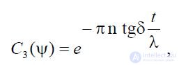 , (16.26)
where tg (zeta) is the loss tangent in the dielectric; t is the current thickness of the lens corresponding to the direction (psi) of the wave incident on the lens.
In the first approximation for dielectric lenses with low losses can be considered constant  The same situation holds for metal plate lenses.
Factor form  depends on the properties of the selected feed. Если же линзовая антенна располагается в раскрыве рупора, то амплитудное распределение в падающем на линзуполе приблизительно совпадает с амплитудным распределением
основного волноводного типа волны в рупоре. Так, для пирамидального рупора с волной типа 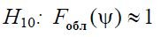 — вплоскости E и
 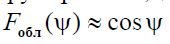 — вплоскости H.
После определения Е(М) по формулам (16.19) — (16.26) найденное амплитудное распределение в раскрыве осесимметричной или цилиндрической линзы можно аппроксимироватьоднойиз подходящих функций.
В осесимметричных линзовых антеннах с диаметром раскрыва dp удобной аппроксимирующей функцией является функция:
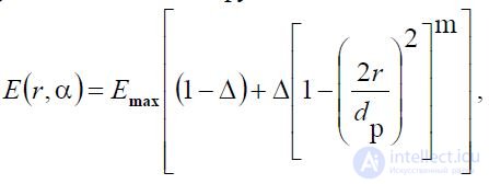 (16.27)
где E max — максимальное значение  на раскрыве; m =1, 2, 3, ... – целое число;
 — произвольный параметр.
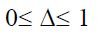
Значения m и дельта подбирается из условия наилучшей
аппроксимации Е(r,альфа). При этом диаграмма направленности  антенны записывается в следующем виде:
(16.28)
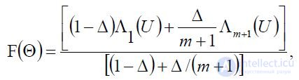
где Лm(U) — лямбда-функция m-ого порядка;
 — обобщенная угловая
2 координата. В цилиндрических линзовых антеннах с размером апертуры dpl возможна следующая аппроксимация амплитудного распределения:
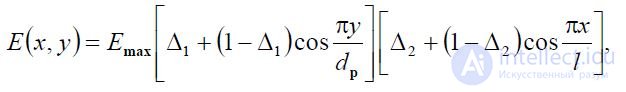 , (16.29)
где дельта 1 дельта 2 — подбираемые параметры, лежащие в интервале [0, 1]. При этом диаграмма направленности записывается в виде:
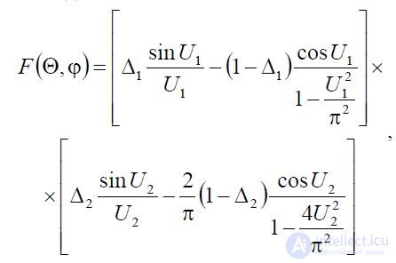
, (16.30)
Where 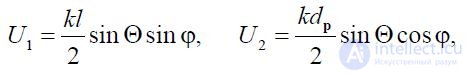
 — угловые координаты сферической системы координат, ось OZ которой перпендикулярна раскрыву антенны.
На КПД линзовых антенн влияют отражение от поверхности линзы, активные потери в линзе, а также то обстоятельство, что часть мощности облучателя проходит мимо линзы. Сделаемоценку этих потерь. Средний КПД, обязанный потерям мощности на отражение р , равен
 . (16.31)
Для уменьшения отражений от линзы на ее поверхность наносится согласующий слой
д
другого диэлектрика с диэлектрической проницаемостью д n и толщиной . This
4 слой выполняет функции четвертьволнового согласующего трансформатора. Однослойное покрытиеобеспечивает хорошее «просветление» линзы в относительно узкой полосе частот в несколько процентов. Для расширения полосы частот применяют многослойные согласующие покрытия.
КПД, обязанный активным потерям в линзе, зависит от угла диэлектрических потерь следующим образом:
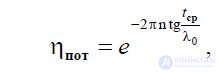 , (16.32)
где через t — обозначена средняя длина пути луча в линзе. КПД облучателя л можно
можно определить через его диаграмму направленности. Предполагая, что обл F симметрична
относительно оси линзы, получаем:
.
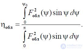
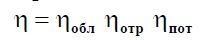
Полный КПД линзовой антенны равен:
Расчеты показывают, что полный КПД диэлектрических линзовых антенн зависит от качества применяемых диэлектриков и при правильном конструировании линзы лежит примерно винтервале 0,7…0,9.
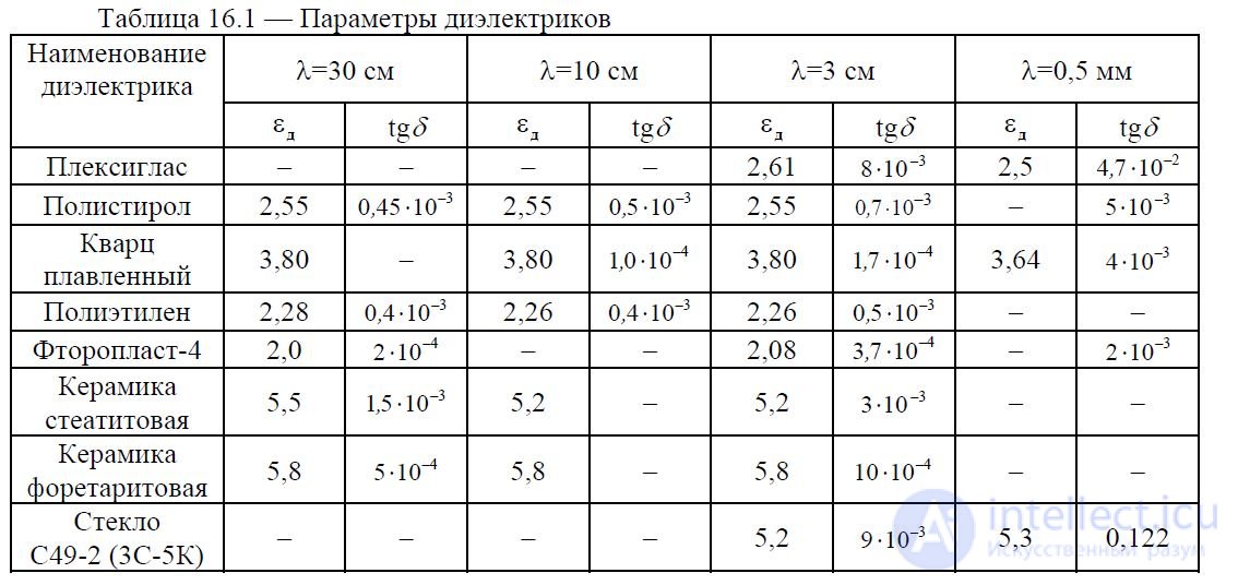
В таблице 16.1 приведены характеристики ряда диэлектриков, которые могут быть использованы для изготовления радиолинз.
В СВЧ-диапазоне также применяются линзы из искусственного диэлектрика, имеющего малые потери и вес. Искусственный диэлектрик обычно состоит из пенистого
г / см 3
полистирола (с плотностью (0,03…0,1) и относительной диэлектрической
проницаемостью близкой к единице ( є д =(1,03…,10)) с расположенными в нем небольшими металлическими частицами, изолированными друг от друга ( металлические частицы могут иметьформу шариков, дисков, пластин, лент). Линейные размеры этих частиц, параллельные вектору электрического поля, выбираются малыми по сравнению с рабочей длиной волны. Такие линзы,образованные из искусственных диэлектриков, называют металлодиэлектрическими линзами. Коэффициент преломления n металлодиэлектрических линз зависит от размеров и формыметаллических частиц и от их количества в единице объема. Величина n обычно выбирается в пределах 1,5…1,6, как и для обычных диэлектрическихлинз.
Специальные типы линзовых антенн. В рассмотренных выше линзовых антеннах произвольное изменение положения луча в пространстве возможно лишь при механическом вращениивсей антенны. Небольшое отклонение максимума диаграммы направленности от фокальной оси одноповерхностных линзовых антенн возможно при смещении облучателя из фокуса вперпендикулярном к оси линзы направлении. При этом максимальный угол отклонения  , определяемый из условия ограничения возникающий в раскрыве
кубической фазовой ошибки величиной  , равен:
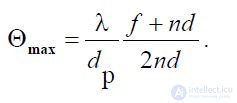 . (16.35)
Таблица 16.1 — Параметры диэлектриков
For frequently used values of f, n and d y, the deviation angle does not exceed two to three widths of the radiation pattern. There are lens antennas in which changes in the beam direction in a limited and even in a wide angular sector can be accomplished only by moving the feed. Such antennas include lens antennas of saplanatic and bifocal lenses, as well as spherical and cylindrical Luneberg lenses.
Aplanatic and bifocal lenses are among the two-surface refracting lenses (see. Fig. 16.2, e, f). The additional degree of freedom associated with the choice of the second refractive surface allows one to choose this surface from the condition of ensuring the maximum sector of a low-distorted scanning with a maximum radiation pattern due to the movement of the feed.
Bifocal lenses have two foci located symmetrically on both sides of the lens axis, and therefore have greater potential for expanding the scanning sector than single-focus lenses. The method of calculating aplanatic and bifocal lenses is rather cumbersome.
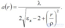
The spherical Luneberg lens is a ball of radius R, made of a material with a refractive index, depending on the radial coordinate r (fig. 16.8) according to the law:
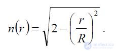 . (16.36)
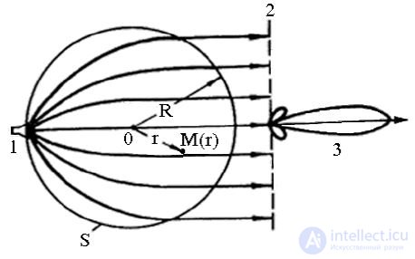
Fig. 16.8 - To the explanation of the principle of action of the Luneberg lens
When the phase center of the irradiator 1 is located on the spherical surface S of the Luneberg lens, all the rays emanating from the lens turn out to be parallel, and the direction of the radius coincides with the direction of the diameter drawn from the location of the phase center of the irradiator. Thus, the Luneberg lens converts a spherical wave front, diverging from a point located on its surface, into a flat front 2 and thus forms the most directional radiation pattern 3.
Due to the spherical symmetry of the lens when moving the irradiator on its surface, an undisturbed two-dimensional scanning of the antenna beam in a solid angle of 4 steradian is performed.
As an irradiator in the Luneberg lens, the open end of a waveguide or a small horn can be used. Placing several m 1, , M of such irradiators along the surface of the lens, we obtain the so-called multipath antenna system, in which each irradiator corresponds to its own directional pattern. This, in turn, allows for simultaneous (parallel) review of a significant sector of space using sharply directed diagrams.
The required change in the refractive index (16.36) can be obtained by using foam polystyrene, the density of which increases in the radial direction.
The spherical lens directivity pattern is close to a circular, in-phase aperture radius R with a uniform amplitude distribution.
The analogue of the one-dimensionally scanning Luneberg lens is a cylindrical lens of circular cross section, the refractive index of which varies according to the law:
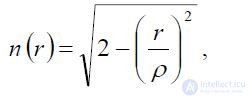 , (16.37)
where p is the radius of the cylinder; r is the distance from the cylinder axis.
A cylindrical lens is usually made of two round coaxial metal plates, the space between which is filled with a dielectric (Fig. 16.9).
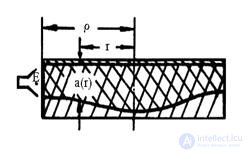
Fig. 16.9 - Cylindrical lens
The lens is excited by a rectangular waveguide or a horn with a wave of H10, with the electric field vector parallel to the plates. The phase velocity of the wave between the plates depends on the distance a (as in a plane parallel waveguide). Therefore, the necessary change in the refractive index (16.90) can be obtained by appropriately selecting (r) by law:
 (16.38)
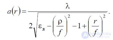
One of the design flaws of a highly directional Luneberg lens is rotation when scanning the irradiator beam over a large radius surface. This disadvantage is partially eliminated in the modified Luneberg lens, which represents a cylinder of radius with a refractive index changing according to the law:
 (16.39)
where r is the distance from the center of the cylinder.
The irradiator in such a lens should be located at a distance f from the center of the lens. An example of a cylindrical Luneberg lens is shown in fig. 16.10.
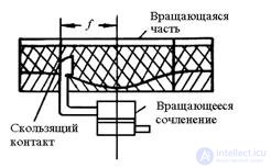
Fig. 16.10 - Modified cylindrical Luneberg lens
The change in the distance between the plates must obey the following law:
(16.40)
Dielectric lens antennas with a flat radiating aperture have limited use as biased antennas, since they are inferior to mirror antennas in overall weight and cost characteristics. More promising are Luneberg lenses, in which wide-angle electric scanning can be performed and a wide-band operation mode. However, these antennas also have relatively large dimensions and cost, and are intended mainly for ground and partly shipborne radio systems.
Metal plate lenses as independent antennas are also used quite rarely, but are widely used in conjunction with highly directional horn antennas. Metal plate lenses can significantly reduce the length of highly directional horn antennas and increase their gain. Various forms of small electrical lenses are also used in the design of horn feeds of mirror antennas. The use of corrective lenses in such irradiators makes it possible to form the required irradiator radiation pattern.

Comments
To leave a comment
Microwave Devices and Antennas
Terms: Microwave Devices and Antennas