1. The rod dielectric antenna (see Figure 14.1, e) consists of a solid dielectric rod, excited by a waveguide segment. The material for the manufacture of the rod are dielectrics with a very small value of the tangent of the angle of loss (of the order of 10 -3 - 10 -4 ) and the value of the relative dielectric constant of the order of several units (polystyrene, teflon, steatite).
The cross-section of the rod can be rectangular, square, however, the most widespread dielectric antennas of circular cross section.
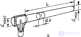
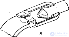
Fig. 14.7. Power supply methods for dielectric rod antennas:
a - coaxial feeder; b - waveguide.
At a wavelength of 10 cm or more, the dielectric antenna is usually powered by a coaxial feeder (Fig. 14.7, a).
In this case, the primary exciter is an asymmetrical vibrator located inside a segment of a circular waveguide that is short-circuited on one side. The length of the vibrator and its distance from the end of the waveguide are selected for reasons of matching the antenna with the power feeder.
In the centimeter wavelength range, a waveguide is usually used to power the dielectric antenna. In this case, to match the rod with the waveguide, a matching chamber is placed at the end of the waveguide and the initial section of the dielectric rod is cut into a cone (Fig. 14.7,6).
An approximate calculation of the parameters of a dielectric antenna is based on the assumption that the same waves propagate along a dielectric rod as they do along an infinitely long dielectric waveguide. With the above methods of excitation along the rod, the main asymmetric HE 11 wave , whose structure is shown in Fig. 14.8, can propagate. The wave type is NOT 11 , is surface [3]. A part of the wave energy is transferred by the rod, and a part by the space surrounding the rod. The intensity of the surface wave decreases in the radial direction.
Fig. 14.8. The structure of the field wave type NOT 11 .
The phase velocity at which an electromagnetic wave propagates along a dielectric rod depends on the dielectric constant of the material of the rod, as well as on the ratio of the diameter of the rod d to the wavelength (Figure 14.9). From fig.14.9 it is seen that with decreasing rod diameter (in comparison with the wavelength) the phase velocity approaches the speed of light. For each value of the dielectric constant there is such a value of the ratio d / l , at which these velocities are almost equal. The diameter of the rod corresponding to this condition can be determined by the formula:
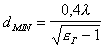 . (14.7)
As is well known (see §3.4), in longitudinally radiating antennas, one-sided directivity is achieved due to the fact that the power phase of each subsequent antenna element is lagging in relation to the power phase of the previous element. In a dielectric rod antenna, this condition is performed by using a rod with a diameter that gradually decreases towards the end (see Fig. 14.7, a). If the diameter at the end of the rod is chosen in accordance with condition (14.7), then there is no reflection from the end, a traveling wave propagates along the rod, with each subsequent element of the rod being fed with a lag in phase compared with the previous one.
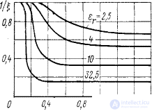
Fig. 14.9. The dependence of the reciprocal of the deceleration coefficient (1 / x = v F / s) of the HE 11 type of waves on the d / l ratio and on e Г.
In the case of a cylindrical rod, part of the energy is reflected from its end and is emitted predominantly in the opposite direction. This leads to the growth of the rear lobes and due to the interference of the fields to an increase in the level of side lobes.
For undistorted formation of ND, it is important that no higher types of waves propagate along the rod. The analysis shows that for this purpose the maximum diameter of the rod must satisfy the inequality
d MAX =>  . (14.8)
When calculating the radiation field, the conical rod is replaced with a cylindrical one, the diameter of which is approximately equal to the average diameter of the conical rod.
d ” ( d MAX + d MIN ) / 2.
Under the radiating aperture of the antenna understand the side surface of the rod. Since the components of the electric and magnetic fields that are tangent to the surface of the rod are known from solving Maxwell’s equations for an infinite dielectric waveguide, it is possible to determine the radiation field of a rod of finite length [2]. The antenna pattern of the antenna is expressed by formula (14.2), where f с ( q ) is the multiplier of the system, defined by formula (14.3). As for the factor of the single emitters of which the continuous system consists, it in the E and H planes, respectively, has the form:
f 0 Е ( q ) = J 1 (ka sin q ) / kasin q , (14.9)
fo H ( q ) = cos q J 1 (kasin q ) / kasin q ,
where a = d / 2, and the angle q is measured from the axis of the rod. Here, a single emitter should be understood as a portion of the surface of a rod of length dz (see Fig. 14.7, a). Since usually L >> a , the shape of the pattern is determined mainly by the multiplier of the system.
The optimal length of the dielectric rod L of the OPT is determined by the formula (14.4), and the PND - by the formula (3.60). With an increase in the length of the rod, the width of the main lobe decreases if L < L OPT . However, at L > L OPT , the level of side lobes sharply increases and a split of the main lobe can be observed.
Using a single rod antenna, you can get the width of the main lobe is usually not already 15-20 °. If narrower DNs are required, then an in-phase array of rod emitters is used. Note that sometimes the dielectric antenna is used to obtain a funnel-shaped NAM. In these cases, an axisymmetric wave of type E 10 is used .
2. Ribbed-rod antenna (see Figure 14.1, d) consists of a series of parallel metal disks located along the axis of the antenna. For mounting disks serves a metal rod. For the formation of a HE 11 wave , a pathogen can be applied in the form of a horn or a symmetrical vibrator perpendicular to the axis of the antenna, and the back radiation of the antenna in the latter case is eliminated by a disk - reflector.
The calculation of the electrical parameters of a ribbed-rod antenna is performed similarly to the calculation of the parameters of a dielectric rod antenna. The values necessary for calculating the phase velocity of a surface wave propagating along a ribbed rod are given in the literature [1].
It should be noted that the ribbed-rod antenna can be considered as a director antenna, in which round disks play the role of passive vibrators. Since these discs are “thick,” the ribbed-rod antenna is more range in directional properties than a conventional director antenna. The range of a ribbed rod antenna in coordination with the power line depends on the type of pathogen.
Ribbed-rod antennas are used on centimeter, decimeter and meter waves. In the latter case, to reduce weight and sail can drive discs made of mesh or perforated sheet material.
Disk antennas surface waves.
Flat linear and rod antennas of surface waves are one-way directional antennas. In contrast, surface-wave disk antennas (see Fig. 14.1. D, e) are non-directional in the plane of the disk and have a directionality in the plane containing the axis of symmetry of the disk.
A cylindrical surface wave propagates from a pathogen located in the center of the antenna to the periphery of the disk. If you mentally break a disk into a number of sectors, then each of them can be viewed as a longitudinally radiating antenna of surface waves, the main lobe of which is directed towards the movement of the surface wave and is somewhat inclined from the metal substrate (due to the finite dimensions of the disk). DN of the whole antenna has the form of an oblate torus.
The antenna guide is manufactured in the form of either a dielectric or a ribbed metal disk, the thickness of which decreases to the periphery to match the antenna with free space.
To calculate the DN of the disk antenna, determine the preliminary phase velocity of the surface wave, and then calculate the radiation field of the circular aperture of the antenna.
The use of surface wave antennas.
A distinctive feature of surface wave antennas is the small thickness of the guide, which makes it possible to use them as low-protruding (low-power) or non-protruding antennas. It is known, for example, the use of a linear plane antenna as a glide antenna built flush into the landing strip at the aerodrome.
Widely used surface wave antennas on aircraft. In this case, the skin of the aircraft plays the role of a metal substrate. The location of the antenna can significantly affect its directional properties. Rod antennas to reduce drag are installed along the longitudinal axis of the aircraft, usually in its nose or tail. Rod antennas are also used as irradiators of mirror antennas.
In conclusion, we note that the lack of surface wave antennas is a relatively large level of side lobes. Antennas with a dielectric guide have noticeable losses, and as the wavelength increases, their weight increases dramatically. To reduce weight, rod dielectric antennas of hollow (tubular) construction are sometimes used.

Comments
To leave a comment
Microwave Devices and Antennas
Terms: Microwave Devices and Antennas