The most widespread surface absorbing waveguide attenuators, which are a segment of a waveguide with a plate placed in it, made of absorbing material or a dielectric, on which a thin absorbing layer is applied.
Surface attenuators are widely used both as fixed and as variables. Structurally, surface attenuators are divided into three types:
knife-type attenuators;
attenuators with a plate (or plates) moving from a narrow wall to the center of the waveguide;
polarization attenuators.
Knife-type attenuators are a segment of a waveguide, into which an absorbing plate with bevels is inserted through a longitudinal slit and in the middle of a wide wall for alignment (Fig. 5.2, a). Since the wave type H 10 propagates in the waveguide , there are no transverse currents in the middle of the wide wall and, therefore, a longitudinal slit cut exactly in the middle of the wide wall will not radiate and affect the field structure inside the waveguide. At the maximum immersion of the plate in the waveguide, the attenuation introduced by the attenuator will be maximum. The initial attenuation of such attenuators is of the order of 0.3 - 0.5 dB, the maximum attenuation of the order of 20-40 dB, K bv of the order of 0.85 - 0.95. The surface resistance of the absorbing plates 150-400 ohm / cm 2 .
In the centimeter wavelength range, carbon coatings are most widely used as absorbing coatings for dielectric plates, and in millimeter wavelengths, nichrome coatings are used. The maximum input power of such attenuators is about 0, 1 watt.
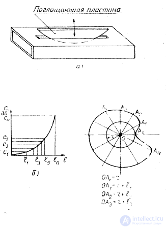
Fig5.2. Variable knife attenuator: a - scheme: b - graduated curve: c - cam.
For attenuators with low accuracy and relatively small permissible K bn dielectric plate, which serves as the basis for the absorbing coating, can be produced from a getinkax or other dielectric with average qualities in terms of stability of parameters depending on temperature, humidity and time. For accurate attenuators, the plate should be made of such dielectrics as quartz, mica, and ceramics.
When designing attenuators for large input powers, the absorbing plate is made entirely from absorbing materials. For example, attenuators with an absorbing plate made of reinforced SKB-90 can withstand power up to 3 watts.
To date, there are no exact methods for calculating the sizes of absorbing plates. Its length with bevels for matching lies within (3.5 - 6) l 0 , where l 0 is the average wavelength of the working range.
To linearize the curve of the dependence of the attenuation on the immersion depth of the absorbing plate, cams with a special profile are used, which allow the insertion of an absorbing plate according to a certain law. The cam profile is calculated on the basis of a graph of the dependence of the attenuation of the absorbing plate on its immersion depth C dB = f (l). This graph is based on experimental data. Below we will consider one of the methods for calculating the cam profile for the C db = f (l) curve shown in Fig. 5.2, b.
The entire attenuation range of the attenuator is divided into n equal parts and the curve C db = f (l) contains the values l 1 , l 2 , l 3 , etc. Then, a circle with radius r is drawn, which determines the initial position of the absorbing plate (zero attenuation ) rice 5.2, c. The circumference is divided into (n + 1) parts. Through the divisions into circles and center, straight lines are drawn. On the first straight line, the distance r + l 1 to the 2nd is laid down - r + l 2 , etc. The А 1 , А 2 , А 3 , etc. points define the cam profile.
The main disadvantages of knife-type attenuators are the significant dependence of attenuation on frequency and low accuracy. Usually they are used as decoupling. Knife-type attenuators can be created throughout the practically applicable range, including the millimeter range.
Attenuators with a plate moving from the narrow wall to the center of the waveguide are a segment of the waveguide in which the absorbing plate is placed parallel to the narrow wall (Fig. 5.5, a). The plate is mounted on a dielectric rod that allows you to move it from the narrow wall to the center of the waveguide. When placing the absorbing plate in the center of the waveguide, that is, at the maximum of the electric field intensity, the attenuation of the attenuator will be maximum. To align the plate with the waveguide, bevels are made on it.
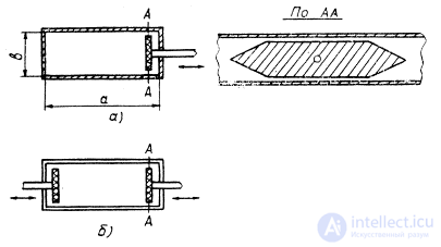
Fig. 5.5. Variable attenuators with absorbing plates moving from a narrow wall to the center of the waveguide: a - with a single plate; b - with two plates.
In addition to attenuators with one absorbing plate, attenuators with two plates simultaneously inserted into the waveguide have been used (Fig. 5.5, b). They allow for greater attenuation and are less frequency critical. The frequency range of their order of 50%, and at attenuators with one plate about 30%. The limits of attenuation of such attenuators are about 0.3 - 40 dB, K bv » 0.85 - 0.95.
The choice of material for the plates, their coatings is made from the same considerations as for knife-type attenuators. An absorbent coating is usually applied to one side of the dielectric plate. To reduce the initial attenuation, the plate is installed with an absorbing layer in the direction of the nearest narrow wall. If the plate is completely covered with an absorbing layer or made entirely of absorbing material, the initial attenuation of such attenuators is of the order of several decibels.
At certain heights of the plates, a resonance occurs, which significantly degrades the characteristics of the attenuator. Usually the plate height is of the order
l l = (0.85 - 0.87) b, (5.7)
where b is the size of the narrow wall of the waveguide.
The length of the plate is usually chosen within
1 = (2-5) l in , (5.8)
where l in - the wavelength in the waveguide.
The maximum attenuation of attenuators with plates of such length lies in the range of 20-40 dB. Plate thickness is taken about 0.5 - 3 mm. The length of the bevels of the plate to ensure good matching is taken approximately equal to the wavelength. For linearization of the graduation curve, cams are used, the calculation of which profile is given in the previous section.
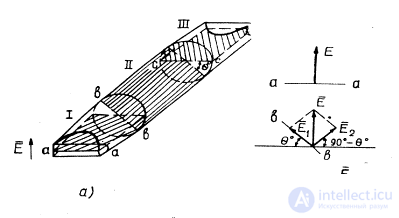
Fig. 5.6. Polarizing attenuator: a - attenuator circuit; b — vector diagrams
Attenuators of this type have approximately the same drawbacks as knife-type attenuators. The range of their use is somewhat narrower than knife-type attenuators. Considered attenuators are not used in the millimeter range because of the small size of the used waveguides.
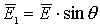
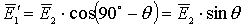
Polarization-type attenuators structurally consist of three full-flow sections - I, II, III (Fig. 5.6, a), in which dielectric plates are placed, covered with an absorbing layer and separating the waveguide sections into 2 equal parts. In the extreme sections (I, III), the absorbing plates are located in one plane. The middle section II is a segment of a circular waveguide and can rotate around a longitudinal axis together with an absorbing plate. Extreme sections - I and III are transitions from a rectangular to a circular waveguide. With the help of these transitions, the H 10 wave for a rectangular waveguide is transformed into a H 11 wave for a circular wave guide and vice versa. The absorbing plates in the extreme sections are arranged so that the lines of the electric field of the propagating wave are normal to the plane of the absorbing plates. If the absorbing plate of the middle section is located in the plane of the outer plates ( q ° == 0 °), then the wave will pass through the attenuator without attenuation. When the middle section is rotated at a certain angle q °, the electric component of the electromagnetic wave can be decomposed into two components: parallel  and perpendicular
  to the plane of the absorbing plate (Fig. 5.6, b):
 (5.9)
(5.9)
 .
.
Electrical component parallel to the plate II section - , will be absorbed by the plate, and on the normal component the plate will have no effect. Component at the entrance of section III will be at an angle (90 ° - q °) to the absorbing plate of section III. It, in turn, can be decomposed into two components: parallel  and perpendicular
  to absorbing plate section III.
 ,
,
 . (5.10)
The normal component is without weakening will pass through section III, and the component completely absorbed.
Thus, the transmission coefficient by intensity will be equal to
k = cos 2 q , (5.11)
in power - k 2 = cos 4 q . (5.12)
Attenuator attenuation in decibels will be
C == -40 lg cos q db. (5.13)
The resulting expression shows that in the absence of reflections from the ends of the plates and in the case of an infinitely large absorptive capacity of the plates, the attenuation of the attenuator depends only on the angle of rotation of the plate of the middle section and does not depend on the frequency. The frequency range of such attenuators is limited by the waveguide. Polarization type attenuators are mainly used as precision ones. Typically, the initial attenuation of such attenuators is of the order of 1-2 dB, the maximum attenuation of the order of 40-60 dB, K bv » 0.87 - 0.9, the permissible power dissipation is up to 1 watt.
The choice of the diameter of a circular waveguide is made from the condition of the existence of only the main type H 11 wave and the absence of higher types of waves (primarily E 01 and H 21 waves). The presence of higher types of waves leads to significant errors. The attenuation of the attenuator will have the greatest impact the H 21 type wave , since the E 01 wave is absorbed by the plate. This becomes clear when considering the field structure of these waves. Consequently, the condition of the existence in the circular waveguide only the main wave type is written
 (5.15),
where l CRN21 is the critical wavelength type H 21 ,
l CRN11 - critical wavelength type H 11 ,
l is the working wavelength.
Or, substituting the values of critical wavelengths,
2.057r < l <3.412r,
where r is the radius of the circular waveguide.
Hence, the condition for choosing the radius of a circular waveguide is written:
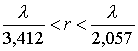 . (5.16)
The most technological design will be in the event that the diameter of a circular waveguide is equal to the diagonal of a rectangular waveguide. In this case, condition (5.16) is satisfied.
The length of the plate of the middle section is selected based on the value of the required maximum attenuation. For example, to obtain attenuation of 45 dB in attenuators with nichrome coating of absorbing plates, the length of the middle section is taken as
l = (3 - 5.5) l max . (5.17)
As the basis of absorbing plates, mica is usually taken, which has a small thickness and a stable shape. Absorbent coating is usually nichrome or platinum.
The length of the transition from a rectangular waveguide to a circular one is chosen within
l lane = ( 2-4) l max , (5.18)
here l max is the maximum wavelength of the working range in the waveguide.
The advantages of polarization attenuators are:
broadband (there is practically no dependence of attenuation on frequency);
the possibility of calibration by calculation;
no dependence of the attenuation on the change (in some limits) of the surface resistance of the absorbing plates.
The disadvantages include various design and technological difficulties. The error due to the resolution of the displacement mechanism increases with increasing angle q , that is, with increasing input attenuation. So, for example, if the permissible error is 0.1 db with 45 db attenuation, then the resolution of the displacement mechanism should be equal to 5 angular minutes. Thus, high requirements must be placed on the design of precision attenuators.

Comments
To leave a comment
Microwave Devices and Antennas
Terms: Microwave Devices and Antennas