Lecture
Planar antennas. Principle of operation. Directional pattern. The design of the planar antennas.
One of the main trends in the development of modern microwave electronics is microminiaturization of electronic equipment (REA). Significant advances in this direction were obtained with the widest use of the latest achievements of microelectronics, both in terms of low-frequency sides of radio electronics and its microwave modules. It is known that the qualitative characteristics of electronic equipment are largely determined by the properties and structural-electrical parameters of its antenna-feeder device (AFU). Especially noticeable gain in mass-dimensional parameters of electronic equipment is achieved when moving from microwave modules from planar integrated circuits (ICs) microwave to three-dimensional integrated circuits (OIS). overall, weight, cost, design and other parameters. This applies in particular to airborne AFUs, where often the limiting capabilities of electronic equipment are determined by the engineering and technical level of development of the antenna structure. Indeed, artificial earth satellites and manned spacecraft of the 60s – 70s. had from 15 to 120 antennas with a complex and extensive feeder system.
At the same time, the AFU occupied approximately 20% of the area of the object. It is obvious that it is possible to fulfill the numerous and stringent requirements for the AFU in the presence of printed conformal antenna structures of small thickness.
Microstrip antennas (MPA), manufactured by IP technology, provide high dimensional repeatability, low cost, low metal consumption, overall dimensions, mass.
MPAs are capable of emitting electromagnetic waves with linear and rotating (circular and elliptical) polarization, allow convenient design solutions to ensure work in two- or multi-frequency modes, easily allow to combine many emitters into antenna arrays and place them on surfaces of complex shape. In addition, MPA have high aerodynamic, mechanical and temperature characteristics.
Microstrip radiators as independent MPA and as radiators of antenna arrays (including phased ones) have a great variety and differ in their working principles, design implementation, radiation characteristics, and the presence of hybrid connections with other microwave devices.
The various signs that can be used as the basis for the classification of IPA are very diverse. By design features and an approach to analyzing an MPA, one can distinguish plane antennas of the resonator type and antennas, which consist of curvilinear microstrip structures, these include spiral and vibrator antennas, as well as antennas having composite and loaded microstrip structures.
A typical MPA design is a thin (on the order of tens of microns) flat conductive plate of one form or another, placed on a dielectric layer — a substrate with thickness h = (0.003 ... 0.08) λ, bounded below by the conductive screen plane. Here λ is the wavelength in free space.
As a substrate, materials with a relative permittivity ε = 2 ... 10 are usually used, but, depending on the applications, a wider range of ε values is possible. The main requirement for the substrate material is small losses, characterized by the loss tangent tgδ. Substrates of cellular material with ε = 1.05 or MPA with an air gap have the lowest losses and provide the greatest radiation efficiency of the antenna. Increasing the ε value of the substrate used allows you to create an antenna of smaller overall dimensions with a wider DN.
The MPA plates most often have a rectangular or round shape, but in principle any shape with a known resonant frequency is possible. By choosing the plate shape, it is possible to significantly improve the coordination of the MPA with the feeder line, or to realize circular polarization of the antenna radiation.
Printed antennas (PA) are resonant, so they can function in a narrow band of frequencies, approximately (1 ... 3)%. The bandwidth of the PA of known shapes is approximately proportional to the thickness of the substrate, the square of the resonant frequency and inversely proportional to the square root of of the substrate. The natural way to increase broadband without complicating the antenna design, which is to use thicker substrates with moderate values of the dielectric constant of the material, has limited capabilities, since with increasing dielectric thickness, there are opportunities for higher types of surface waves, which dramatically reduces the radiating efficiency of the antenna. It is known that the effect of a sharp decrease in the efficiency of radiation
spatial waves at the time of the appearance of the LE 1 wave in the PAS of the electric and magnetic types. An increase in the substrate thickness can lead not only to the appearance of higher types of surface waves in the outer region, but also to the excitation of higher types of waves in the PA. These waves can serve as a source of significant cross-polarization field components. In the case of a rectangular antenna, the nearest higher type may be a type orthogonal to the basic collar ***, which is especially dangerous at close antenna widths and antenna lengths. . Such structures can also perform the role of multi-frequency PA.
For rough estimates of the DN of a rectangular printed-circuit emitter over a field with the main polarization, it can be considered as the DN of two in-phase end slots with a uniform field distribution. Similarly, the DN across the field with cross-polarization is defined as the DN of two antiphase side slits with an odd field distribution.
Thus, the magnetic currents of the end slits are in-phase and equal-amplitude, and their emission maxima will be directed orthogonal to the plate of the plate.
In fig. 12.1 shows the direction of the magnetic currents on the end and side slots.
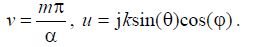
To determine the radiation field in the far-field zone m. M (x0, y0, z0), we use the vector
potential  considering that
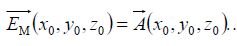
To do this, it is necessary to record the geometric relations for the printed radiator, derivatives of these relations, as well as the current distribution along the radiator length.
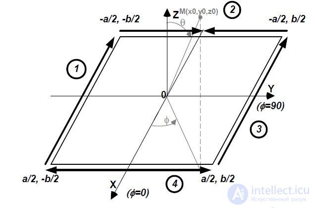
Fig. 12.1 - Direction of equivalent magnetic current along side faces
printed emitter
For side "1":
Where 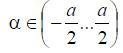
- integration variable, m = 0 ... 1 - coefficient describing the relative level of the pedestal by the contact-current distribution of the current. The limiting cases m = 1 is the cosine of the current distribution (waveguide equivalent), m = 0 is the uniform current distribution; all other cases are the cosine of the current distribution with the pedestal.
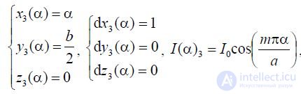
For side "3":
For side "2":
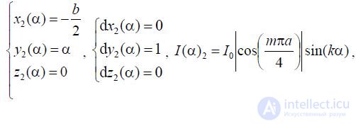
Where 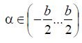 - integration variable
For the side "4":
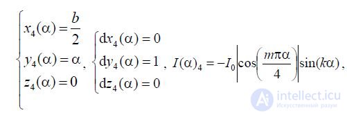
Where 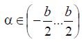 - integration variable.
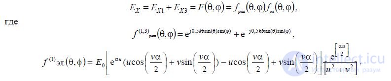
Now for the parties "1" and "3" we can write:
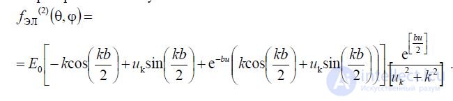
. Solving analytically integrals, we obtain computational expressions for the slots "1" and "3"
Where
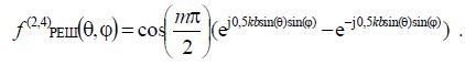
The radiation of the common-mode currents "1" and "3" can be represented as the radiation of a two-element array, the radiation pattern of which is determined by the ratio
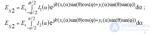
By analogy, the emission of side currents along the y axis on the side “2” can be written as
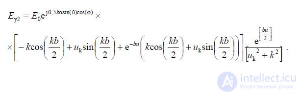
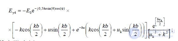
On side “4” the distribution will be antiphase to currents of side “2”.
Where 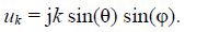
. The sides "2" and "4" are also represented in the form of a two-element lattice, whose multiplier can be written as
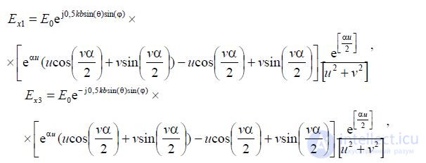
After the conversion, we get
Finally, the expression for the sides "2" and "4" can be written in the form
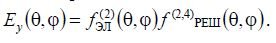
Turning to a spherical coordinate system, for the components of the field of the main polarization, we obtain the relations:

For the cross-polarization of the radiation field generated by the side slits, the following relationships can be written:
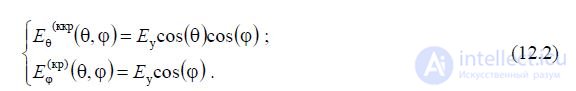
Expressions 12.1, 12.2 are calculated to calculate the field created by the strip transmitter in the far zone.
In the case of a strip radiator based on a conductive area of complex shape, it is necessary to use calculation methods that will take into account the design features of the antenna being developed. This is all the more important in the case of building an antenna array of printed emitters in which the effects of mutual influence will appear.

Comments
To leave a comment
Microwave Devices and Antennas
Terms: Microwave Devices and Antennas