Lecture
1. When connecting segments of transmission lines and nodes, special connecting devices are required. In addition, if the sections of the feeder path are connected with different types of waves, then special transition devices are needed, which are called wave type transformers. They can also be referred to as connecting devices.
The most common specific requirements for all connecting devices are:
- reliable electrical contact at high frequency at the junction;
- minimum of reflections of electromagnetic waves in a given frequency band;
- the minimum level of infiltration of electromagnetic energy through the junction into the surrounding space.
2. Fixed direct connections of coaxial lines are made in the form of high-frequency plug connectors (chips). In fig. 18.14. As an example, one of the standard plug connectors for flexible coaxial cables is shown. This connector, designed for use in onboard aircraft devices, has a sophisticated but robust design. Sealing is ensured by a rubber gasket 1, and reliable electrical contact by the use of spring skirts 2 on the outer and inner wires of the connection.
3. The devices for the fixed direct connection of waveguides are called flanges.
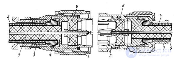
Figure 18.14. Plug connector for connecting coaxial cables:
1 - sealing rubber gasket; 2 - contact spring skirts;
3- central core; 4 - outer sheath; 5 - protective coated;
6 - matching centering washers; 7 - high-frequency dielectric.
At the most simple in arrangement of the contact flanges (Fig. 18.15), the waveguides are tightened with screws 1 and smooth flanges 3, somewhat offset from the planes of the edge 4; this ensures tight connections and reliable electrical contact between the flanges. The guide pins 2 eliminate the displacement of the waveguides.
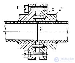
Fig. 18.15. Contact flange for connecting waveguides.
With frequent assembly and disassembly of the connection simple contact flanges unreliable. In these cases, contact flanges with soft (petal) gaskets or contactless throttle-flange connections are used. One of the designs of the latter is shown in Fig. 18.16. The joint consists of a throttle flange 4 and a smooth flange 5. A rubber ring 6 is used for sealing. The plane 7 and the smooth flange form a flat radial line in which the TEM-type wave propagates, excited by longitudinal currents on wide walls broken by the gap 1 between the waveguides. The length of the radial line in the vertical section is l 1 = l / 4. At the end of this line, in section 2, galvanic contact is made between the flanges. The annular undercut between sections 2 and 3 is a segment of a coaxial line, ground at the end.
Length of this line  where
where  - wavelength of coaxial-waveguide lines of *** type H 11 . It is these collisions that are shown in fig. 18.16, are excited in the annular recess.
Zero resistance at section 3 by a quarter-wave line transforms into high resistance at section 2, where good contact is not required. This large resistance by the quarter-wave segment l 1 is again transformed into a very small resistance at the entrance of the gap 1. The idea of a throttle connection, therefore, is that the unreliable galvanic contact between the waveguide ends is replaced by a reliable short circuit made at a distance of half a wave from the junction of the ends waveguide.
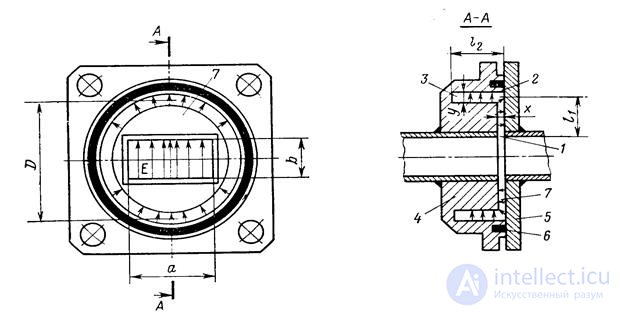
Fig. 18.16. Throttle flange waveguide connection.
If a large isolation (60 dB or more) is required between different parts of the transmitting / receiving feeder path, then the quality of galvanic contact in section 2 is subject to increased requirements so that electromagnetic energy does not leak through it. The dimensions l 1 and l 2 depend on the operating frequency:
l 1 " l / 4,  , (18.8)
where pD = lcr11 is the critical wavelength of a collar *** of the type H 11 in the undercut; D is the diameter of the average circumference of the undercut. The width of the bandwidth of the considered construction is the greater, the greater the ratio of y / x.
If the flanges are not installed precisely enough against each other, i.e. somewhat shifted or rotated, then in the annular undercut, in addition to the H 11 wave, an asymmetric H 21 wave is excited, which increases the reflection from the junction and reduces the passband. Some more complicated choke-flange connections with incomplete ring undercut are free from this disadvantage (fig. 18.17).

Fig. 18.17. Throttle flange waveguide connection with an incomplete ring undercut.
4. Mobile connections allow to displace and rotate in a small range one part of the feeder path relative to another. Flexible connections include flexible waveguides. They are divided into two main classes - non-resonant and resonant. Non-resonant flexible waveguides have either corrugated walls (Fig. 18.18, a), or walls wound spirally with a track-type engagement (Fig. 18.18, b). The latter construction is more perfect, since besides bending it provides twisting.
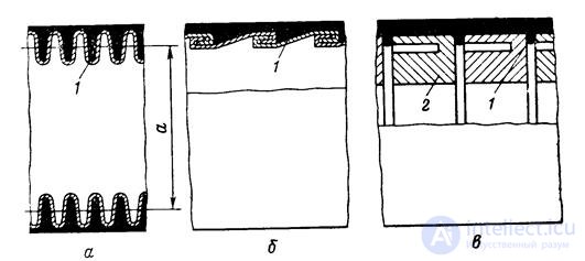
Fig. 18.18. Flexible waveguides.
The resonant flexible waveguide (armored waveguide) (Fig. 18.18, c) consists of a series of choke sections 2, performing a high frequency closure at the points of waveguide rupture. The gaps between the sections provide the possibility of small displacements of the sections. The larger sections, the greater the angle of curvature or twist. The throttle sections are made in the form of washers with a thickness of approximately L / 4; in this case, the reflections of the waves arising in the adjacent waveguide breaks are mutually compensated. Washers are mounted in a rubber casing 1, providing the necessary flexibility and tightness. The shell waveguide has increased losses due to the leakage of electromagnetic energy into the gaps between the sections and therefore is always used in the form of short segments. A flexible metal mesh is used to screen the resonant flexible waveguide.
In coaxial lines, mobile connections are made using flexible cables. These cables are sometimes used as mobile connections between waveguides.
5. Waveguide corners and bends (rice. 18.19) are used when changing the direction of transmission of electromagnetic energy by a rectangular waveguide with a wave of type H 10 and connect the direct segments of the waveguides. These devices are made in the form of separate units (and in this case they have flanges on both sides), and in the form of bends of a single piece of the waveguide.
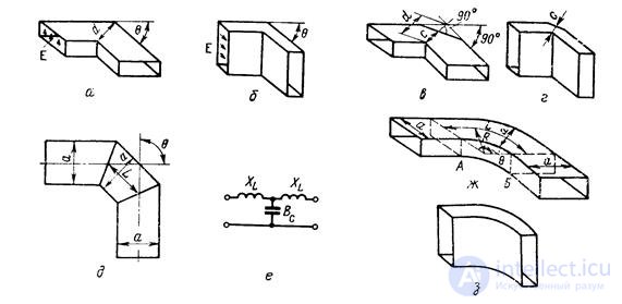
Fig. 18.19. Waveguide corners and bends.
The simplest device for an abrupt change in the direction of transmission is a waveguide angle. Corners can be made both in the E- and in the H-plane. In addition, the corners can be simple and double.
Reactivity introduced into a waveguide with a simple corner of any type is represented by an equivalent circuit in the form of a T-shaped quadrupole with series inductances and parallel capacitance (Fig. 18.19, f). Corners in the H plane (Fig. 18.19, a, c) are mainly inductive resistance (conductivity В C is small), and corners in the E plane (Fig. 18.19, b, d) - capacitive conductivity (resistance X L is small).
A simple corner without compensation (fig., 18.19, d, b) is used in practical constructions only in cases when the angle of rotation does not exceed 30-40 °.
The most widely used in narrowband transmission lines (with a band of 5-10%) is a simple angle with compensation (Fig. 18.19, c, d). By selecting the distance from, it is always possible to achieve compensation of reflections at the average wavelength range. The range properties of a simple compensated E-plane angle are slightly better than H-plane. For power transmission, the ratio of qualities is the opposite.
The double corner (fig. 18.19, d) has two spaced inhomogeneities. Therefore, it is possible to choose the distance L so that the reflections from these inhomogeneities are compensated in a certain frequency band.
In addition to corners, H- and E-plane bends are often used (Fig. 18.19, g, h, respectively). The wavelength in a curved waveguide with sufficient practical accuracy can be considered equal to the wavelength in a direct waveguide. Wave resistance of a curved waveguide is greater than wave resistance of a direct waveguide. The difference is greater, the smaller the bending radius is R. The reflection coefficients in sections A and B have the same modulus, and differ in phase in p, because in section A there is a transition from lower characteristic impedance to greater, and in section B from greater to a lesser extent. Therefore, to compensate for reflections from sections A and B, the distance L between them, measured along the centerline, must be a multiple of the integer number of half-waves, since the phase difference due to the difference in travel between the reflected waves from sections A and B will be equal to zero.
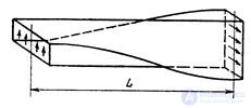
Fig. 18.20. Waveguide twist.
6. Waveguide twists (fig. 18.20) are used to rotate the plane of polarization (most often at an angle of 45 or 90 °). The wavelength in a twisted waveguide is about the same as in a direct waveguide, and the characteristic impedance is slightly increased. Therefore, the length of the twist is chosen from the same considerations as the length of the bend. To work in broadband devices, the length of the twist must be more than 1,5-2L 10 .
7. Wave type transformers are used to connect sections of transmission lines that use different types of waves. These transformers are sometimes referred to as excitation devices.
In practice, seven types of waves are most widely used: Н `` 10 , Н `` 20 and Н `` 11 - in a rectangular waveguide; E ° 01 , H ° 01 and H ° 11 in the round and TEM wave. Accordingly, the number of practical types of transformers for these types of waves is equal to 21. In fact, much more of these devices are used, since the transition between these two types of waves can be carried out using several transformers based on different principles. Below are just a few of the most characteristic designs of these devices.
The basic idea of constructing transitions between lines with different types of waves is that the transition should create an electromagnetic field that has the same components as the field of the required type of wave and, if possible, should not create (or create with low intensity) components contained in the desired type of ox. If the latter does occur, they must be filtered by special types of wave filters that complicate the design of transformers and reduce their dielectric strength and bandwidth.
Transformers of the types of waves, as a rule, are reversible elements of the transmission lines, so the design that provides the transition, say, H `` 10 - E ° 01 , provides a reverse transition, i.e. Е ° 01 - Н`` 10 .
8. Connection of a coaxial line with a rectangular waveguide, shown in Fig. 18.21, is a transformer of type TEM-N `` 10 and is one of the so-called probe transitions.
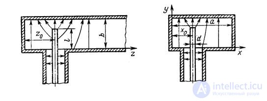
Fig. 18.21. Probe coaxial-waveguide junction.
In this transformer, a segment of the central core of a coaxial cable of length l is an antenna in a waveguide, radiating electromagnetic energy into a waveguide or picking it up from a waveguide. Here the field of the required wave type H `` 10 has the components H x , E y , H z . The probe, which is perpendicular to the wide wall, creates a field with the listed components and, in addition, the components E x , E z of small amplitude due to the curvature of the force lines in the vicinity of the probe. If the probe is deflected from the vertical at a noticeable angle, then the indicated “parasitic” components of the electric field and the accompanying magnetic field will increase dramatically. The fields of these components, creating higher-type waves, will be reactive and the reflections from the transition will also increase dramatically.
At a distance of z 0 from the probe, somewhat smaller than L / 4, the waveguide is shorted on one side by a wall or a piston. In this case, the waves reflected from the wall, when propagating to the right, will form in phase with the waves going to the right directly from the probe (a quarter of the wave to the wall, a quarter of the wave back and a phase rotation on π upon reflection from the metal wall - total 2p). By selecting l, z 0 and x 0 , it is possible to achieve good matching of the coaxial line with the waveguide in a certain frequency band. If the probe is located in the middle of the wide wall (x 0 = a / 2), then the matching is achieved at the specified value of z 0 and at l »0.2l. Probe transitions are the simplest, but they have a narrow bandwidth and lower dielectric strength due to the high concentration of the electric field at the top of the probe.
9. Transformers of types of waves with a T-vibrator (Fig. 18.22) are also among the TEM-H `` 10 transitions. They have a bandwidth of up to 30% due to the fact that the transverse rod ensures uniformity and low dependence on the frequency distribution of the current on the vertical part of the probe. The electrical strength of this design is also great.
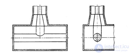
Fig. 18.22. Coaxial-waveguide transition with a T-vibrator.
10. A wedge-shaped transformer of TEM-N `` 10 wave types is shown in fig. 18.23.
In it the usual rectangular waveguide with the help of wedges with a length of (2–3) L transforms into an H-shaped waveguide having a lower characteristic impedance. The gap between the wedges at the point of attachment of the coaxial line is chosen so that the wave resistance of the waveguide and the lines are equal. The transition with wedges is a distributed inhomogeneity with a low level of reflections, so it has almost the same bandwidth as the regular waveguide.
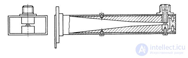
Fig. 18.23. Wedge-shaped coaxial-waveguide transition.
On a similar principle, one of the transitions between the waveguide and the strip asymmetric line is built (Fig. 18.24). Here the sequence is used: a rectangular waveguide, a U-shaped waveguide, a strip line.
11. Transformer of types of waves N `` 10 - H ° 11 . H 10 waves in a rectangular waveguide and H 11 in a round wave have a very similar field configuration. Therefore, the most natural transition for these types of waves is a transition with a smooth change in the size and configuration of the cross section. A sketch of such a transition is shown in Figure 18.25. If the transition length is approximately the wavelength in the waveguide or more, then its transmission bandwidth is equal to the operating wavelength range of a circular waveguide with a H 11 type wave. The dimensions of the rectangular and circular waveguides must be such that only the lowest types of will — H 10 and H 11, can propagate in them in a given operating wavelength range.
12. Transformer of types of waves Н `` 10 - Н `` 20 . In the transitions from a rectangular waveguide with a wave of type H 10 to a rectangular waveguide with a wave of type H 20, in addition to matching, the problem arises of suppressing a wave of type H 10 in a wide waveguide. It is required that power in an unnecessary type of wave does not exceed fractions of a percent of the power of the main wave in the operating range.
According to the electrical characteristics of the most qualitative transition of this type is a smooth transition, a sketch of which is shown in Fig. 18.26, a. A rectangular waveguide splits into two along a narrow wall. Then these waveguides with smooth twists are unfolded and connected so that the directions of the electric vectors in their cross sections are opposite, which is required for the excitation of the H 20 wave. With accurate longitudinal symmetry, the H 10 wave is not excited. Coordination in the frequency band of the order of 50% is achieved in transitions of a length of (2–3) L. Such transitions are difficult to manufacture and expensive.

Fig. 18.24. Wedge-shaped transition from Fig. 18.25 Smooth transformer of waveguide wave types to stripline. N`` 10 - N`` 11 .
For work in a narrow frequency band, a simpler and more compact transition can be applied, as shown in fig. 18.26, b. In this transition, the connection between the waveguide 1c with a wave of type H 10 and waveguide 2 with a wave of type H 20 is carried out using two holes cut in the common wall of the waveguide: narrow - for a waveguide with a wave of type H 10 and end for a waveguide with a wave of type H 20 . The holes are excited by transverse currents flowing through the narrow wall of the waveguide with a wave of type H 10 . The distance between the holes is equal to half the wavelength in a waveguide with a H 10 wave, therefore the fields excited by the holes in a waveguide with a H 20 wave are opposite in phase, which ensures the excitation of a H 20 wave. The diaphragm 3 serves to coordinate and ensure the purity of the wave type H 20 .
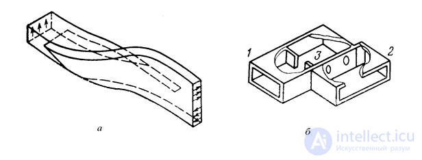
Fig. 18.26. Transitions between rectangular waveguides with waves of types H `` 10 and H`` 20 .
13. Transformer of types of waves N `` 10 - N `` 11 . The simplest way to excite a H 11 wave in a rectangular waveguide is illustrated in Fig. 18.27. К прямоугольному волноводу с близкими размерами поперечного сечения а и б, в котором может распространяться волна типа Н 11 , с торца присоединяется волновод с волной типа Н 10 , причем так, что продольные оси обоих волноводов совпадают, а их главные плоскости развернуты на некоторый угол a . При таком способе соединения в большом волноводе возбуждаются волны типов Н 10 и Н 01 , соотношение амплитуд которых зависит от угла a . Если а=б, то одинаковые интенсивности этих волн получаются при a =45°. При а? б одинаковой интенсивности волн типов Н 10 и Н 01 всегда можно добиться подбором угла a .
Наложение полей волн типов Н 10 и Н 01 образует суммарную волну типа Н 11 , структура электрического поля которой показана на рис. 18.27. Если размеры а и б большого волновода одинаковы, то изображенная на рис. 18.27 структура поля волны типа Н 11 остается одинаковой в любом сечении волновода. Разница в размерах а и б вызовет разность фазовых скоростей волн типов Н 10 и Н 01 , что, в свою очередь, вызовет изменение структуры поля при переходе от одного сечения волновода к другому.
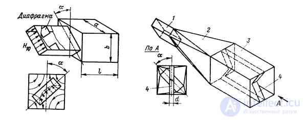
Fig. 18.27. Трансформатор типов Рис. 18.28. Плавный переход между
волн Н`` 10 - Н`` 11 . прямоугольными волноводами
с волнами типов Н`` 10 и Н`` 11 .
Рассмотренный прямой переход имеет узкую полосу по согласованию даже при применении согласующей диафрагмы.
Согласование в широкой полосе частот может быть достигнуто плавным переходом от волны типа Н 10 к волне типа Н 11 , как показано на рис. 18.28. Волна Н 10 в прямоугольном волноводе 1 плавным переходом 2 длиной в (1,5- 2)L переводится в волну типа Н 11 в квадратном волноводе 3.
14. Трансформатор типов волн Н`` 10 - Е° 01 находит широкое применение во вращающихся сочленениях, так как обеспечивает возбуждение в круглом волноводе волны типа E 01 , все составляющие поля которой полностью симметричны относительно продольной оси волновода.
Конструктивно наиболее простым переходом от волны типа H 10 к волне типа Е 01 является переход, изображенный на рис. 18.29,б. Возможность возбуждения в круглом волноводе волны типа Е 01 с помощью показанного соединения круглого и прямоугольного волноводов под прямым углом объясняется наличием в месте перехода составляющей электрического поля, параллельной продольной оси круглого волновода. Так как переход не симметричен, то в круглом волноводе кроме волны Е 01 возбуждается волна типа Н 11 , низшая по отношению к волне типа Е 01 . Плоскость поляризации волны типа Н 11 я круглом волноводе содержит оси круглого и прямоугольного волноводов.
Волна типа Н 11 переносит довольно значительное количество энергии - 1% и больше.
Для подавляющего большинства волноводных трактов современных радиотехнических устройств процентное содержание низших несимметричных типов волн во вращающихся сочленениях должно быть по мощности не более 0,1%. Столь высокую степень чистоты основного типа волны можно получить лишь с помощью специальных устройств, фильтрующих низшие типы волн.
Для фильтрации волны типа Н 11 в переходах от волны типа Н 10 к волне типа Е 01 в узкополосных устройствах применяются короткозамкнутые шлейфы в круглом волноводе (рис. 18.29,а). Как видно из рисунка, волны, идущие влево и вправо по круглому волноводу от места возбуждения, имеют противоположную фазу в равноотстоящих от перехода сечениях. Поэтому, если сделать длину шлейфа L кратной целому числу полуволн волны типа Е 01 , то в круглом волноводе в направлении распространения прямая и отраженная волны сложатся, т.е. при этом будет обеспечено максимальное возбуждение волны типа E 01 . Если одновременно выполнить условие кратности длины шлейфа нечетному числу четвертей длины волны в круглом волноводном шлейфе для волны типа Н 11 , то в направлении распространения в круглом волноводе прямая и отраженная волны этого типа вычтутся, что обеспечивает минимум возбуждения волны типа Н 11 .
Исходя из этих условий, составляются два уравнения, которые определяют оба размера шлейфа - длину и диаметр:
 , n = 1, 2, 3, . . . (18.9)
Так как  ,то длина шлейфа должна быть такой, чтобы на ней укладывались одна полуволна для волны типа E 01 и три четверти длины волны для волны типа Н 11 , т.е. необходимо взять n=1 и m=1. Указанные выше условия можно выполнить и при больших значениях n и m, однако диапазонность перехода резко падает при увеличении длины шлейфа.

Fig. 18.29. Трансформаторы типов волн Н`` 10 - Е° 01 .
Шлейфовые переходы к волне типа Е 01 являются узкополосными устройствами из-за большого объема резонансной камеры, которую представляет собой шлейфовый фильтр.
Более широкополосными и в то же время более компактными являются переходы к волне типа Е 01 с резонансным кольцом в качестве устройства для фильтрации волны типа Н 11 . Эскиз перехода с резонансным кольцом показан на рис. 18.29,в. Круглый волновод соединяется с прямоугольным по верхней широкой стенке. Нижняя широкая стенка прямоугольного волновода одновременно является дном круглого волновода.
The suppression of the H 11 type wave in a circular waveguide is carried out using a resonant filtering ring, the principle of action of which is illustrated in Fig. 18.29, The electric field lines of the E 01 wave are everywhere perpendicular to the ring, and the magnetic field lines are parallel to it, therefore the E 01 wave with accurate centering of the ring does not excite currents in it and the ring has almost no effect on the passage of the E 01 wave . A rectangular waveguide excites in a circular waveguide, in addition to an E 01 type wave, an H 11 type wave with the orientation of the electric field shown in Fig. 18.29, N type field of the wave 11 имеет составляющие электрического поля, касательные кольцу, и возбуждает в нем токи (пунктир на рис. 18.29,г). Если длина кольца примерно равна длине волны в воздухе, в нем наступает резонанс тока. Токи в кольце возбуждают в волноводе также волну типа Н 11 с фазой поля, сдвинутой на p по отношению к фазе возбуждающего поля. Поэтому за кольцом в круглом волноводе возбуждающее и “переизлученное” поля волн типа Н 11 взаимно уничтожаются, что обеспечивает высокую степень чистоты волны типа Е 01 .
Крепление кольца осуществляется с помощью металлических стержней, припаиваемых к кольцу и стенкам волновода так, как это показано на рис. 18.29,г. Стержни располагаются перпендикулярно диаметральному вектору напряженности электрического поля волны типа Н 11 и поэтому не влияют на ее распространение и на резонансное свойства кольца. Эти стержни создают небольшие отражения волны типа Е 01 , которые легко компенсируются согласующими устройствами.
Рассмотренные примеры далеко не исчерпывают все возможные способы возбуждения волны типа Е 01 .
15. Трансформатор типов волн Н`` 10 - Н° 01 используется в линиях передачи электромагнитной энергии на большие расстояния и во вращающихся сочленениях. Как было отмечено, возбуждение волны типа Н 01 в чистом виде является очень сложной задачей, так как при выполнении условий распространения волны типа Н 01 в волноводе могут также распространяться волны типов Н 11 , Е 01 , Н 21 и Е 11 .
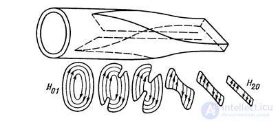
Fig. 18.30. Переход Саусворта.
Наиболее совершенным по согласованию и чистоте волны типа Н 01 является переход Саусворта, схематически изображенный на рис. 18.30. В нем переход к волне типа Н 01 осуществляется путем постепенного изменения конфигурации поперечного сечения прямоугольного волновода с волной типа Н 20 к круглому волноводу. Для работы в широкой полосе частот длина перехода должна быть около полутора-двух длин волн в прямоугольном волноводе с волной типа Н 20 . Диапазонное возбуждение волны типа Н 20 в чистом виде в прямоугольном волноводе может быть осуществлено с помощью перехода, показанного на рис. 18.26,а.
Разработано довольно много способов непосредственного возбуждения волны типа Н 01 в круглом волноводе с помощью прямоугольного волновода с волной типа Н 10 . Многие из этих способов позволяют получить более компактную конструкцию, чем переход Саусворта, однако их диапазонность по согласованию и особенно по чистоте волны типа Н 01 меньше, чем у перехода Саусворта.

Comments
To leave a comment
Microwave Devices and Antennas
Terms: Microwave Devices and Antennas