Lecture
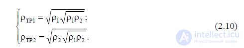
Consider a real transmission line (see Figure 2.1), for which the relations
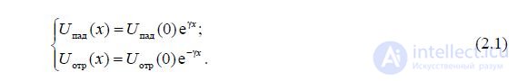
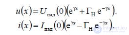
Then
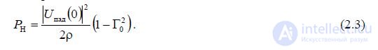
Power, concentrated in any section of the transmission line, is determined by the formula

Power in transmission line load
Transmission Line Input Power

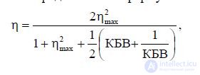
The coefficient of performance (Efficiency) is defined as the ratio of P H to P BX and can be written on the basis of (2.3) and (2.4) as a formula
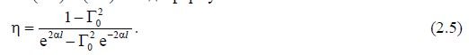
With  KPDpri KBV <1 is determined by the formula
Where 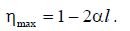 .
.
If the LP has small losses, then the graphs of voltage distribution, input resistance, etc. become “quasi-periodic” (almost periodic), since the modulus of reflection coefficient decreases slightly with distance from the load and the number of graphs also decreases. In this case, to build graphs of the distribution of resistance, you can use formulas (1.16) and (1.17), assuming that
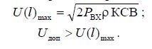
The energy strength of the transmission line is determined by the conditions
Coordination is the provision of traveling-wave mode in LP by including in LP the load between the generator and the generator of a purely reactive matching quadripole (CPS), which transforms the load into a non-reflecting (consistent) one.
The general principle of matching complex resistances is that the matching element is additionally included in the line, the reflection from which compensates for the reflection from the load. At the same time strive to matching element was located as close as possible to the load. This is done to reduce the length of the inconsistent part of the line from the load to the matching element. The inclusion of a matching element is pursued by the following: an increase in the power transmitted to the load; increase the electrical strength of the line; increase line efficiency; elimination of the adverse effect of the reflected wave on the generator.
In the mode of mixed waves in a line, alternating highs and lows of voltage occurs. In places of voltage peaks, conditions for electrical breakdown are facilitated. The elimination of the reflected wave leads to a decrease in voltage at the maximum. Therefore, it is possible to transmit more power along this line or increase its dielectric strength.
The effect of matching on line efficiency is discussed above. It is established that the efficiency is higher, the better the line is matched with the load, i.e. the smaller the modulus of reflection coefficient H.
Methods of narrowband matching. Narrow is considered to be the frequency band, which is a few percent of the average frequency. In this band, an acceptable level of KCB KCBp approval must be provided. A typical graph of the CWS
path from the frequency presented in Fig. 2.1. The specific value of KCVp is determined by the purpose and type of the path, the conditions of its operation and lies within 1.02 ... 2.
In a narrow frequency band, the following devices are used as matching elements: a quarter-wave transformer, a serial loop, a parallel loop, two triple series or a parallel loop.
Such matching devices are used in transmission lines of various types (two-wire, coaxial, strip, waveguide, etc.). The type of transmission line determines the specific design implementation of these devices.
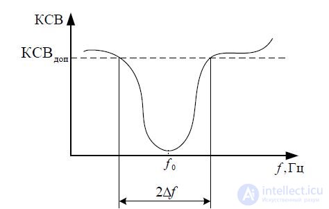
Fig. 2.1 - Dependence of the CWS tract on the frequency
Quarter wave transformer. This device is a quarter-wave line segment with an impedance of "P" included in the break of the main transmission line. Find the place of inclusion of the transformer in the line and its characteristic impedance (see. Fig. 2.2).
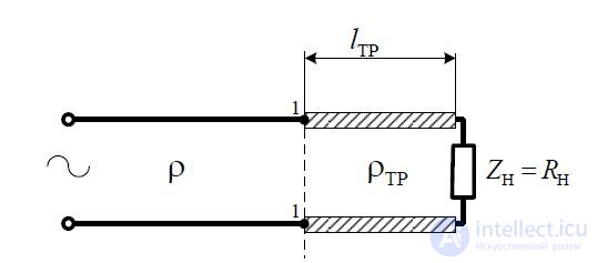
Fig. 2.2 - Quarter Wave Transformer
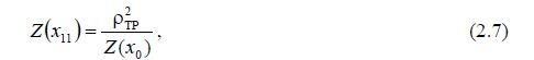
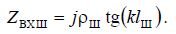
The principle of operation of such a matching device is based on the transforming property of a quarter-wave segment of the line, which in this case takes the form
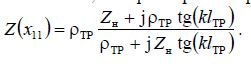
Suppose  then
then
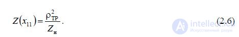
In the case of a complex load, a quarter-wave transformer for matching can be included in such sections of the x 0 line, in which the input resistance of the line is purely active. The input impedance of the line is purely active in sections of the line where the voltage reaches a maximum or minimum. Therefore, a quarter-wave transformer is switched on at maximum or minimum voltage and its characteristic impedance is determined from the relation
where x 0 is the coordinate of the first maximum or minimum amplitude of the voltage on the side of the load.
At the voltage maxima Zx 0 KSV, therefore, when the transformer is turned on to the maximum voltage, its characteristic impedance is Р. At voltage minima
, so when turning on the transformer to the minimum voltage
Zx.
0 CWS TR
Thus, the choice of where the transformer is turned on (maximum or minimum voltage) determines the ratio of its characteristic impedance with the characteristic impedance of the line, and this, in turn, determines the ratio of the geometric dimensions of the transformer's cross section and the line.
Serial loop. The matching device in the form of a serial loop is a segment of a usually short-circuited line of length l Ш , with wave resistance , which is included in the break of one of the wires of the line (Fig.
2.3). Reconciliation is achieved by selecting the place of switching on the loop into the l 0 line and length
plume l w .
l 0

Fig. 2.3 - Matching serial short-circuited loop
Find l and l from the condition of matching the line in the section x l. In this section
0 Ш 0
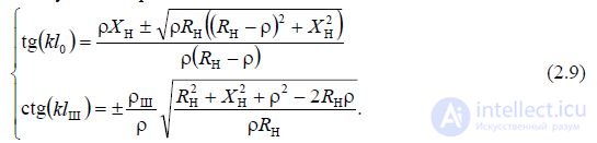
The input reactance of the loop j X Ш l Ш is connected in series with the line resistance Zx Ш Rx Ш j X x Ш . The sum of these resistances should be equal to the wave resistance of the transmission line. The calculated ratios can be
are presented in the form:
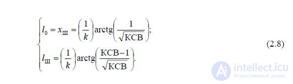
From relations (2.8) it follows that a series loop must be included in such a section of the line where the active part of its input resistance is equal to the characteristic impedance of the line. The length of the loop should be chosen such that its reactance would be equal in magnitude and opposite in sign of the reactive part of the input impedance of the line together switching on the loop.
The disadvantage of this method of matching is that when the load changes, not only the length of the loop changes, but also the place where it is connected to the line. Structurally, it is extremely inconvenient.
Parallel matching loop. The matching device in the form of a parallel loop is shown in fig. 2.4.
_img_44.jpg)
l 0
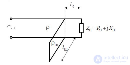 Fig. 2.4 - Matching parallel short-circuited cable
loop x l 0 in the transmission line and the length of the loop l w . The calculated ratios can be represented as:
A parallel loop should be included in such a cross section of the line in which the active part of the input conduction line is equal to the wave conductivity, and the length of the loop should be chosen so that its reactive conductivity compensates for the reactive part of the input conduction line.
The disadvantages of a parallel loop are the same as those of a serial loop: when the load changes, the length of the loop and the place where it is turned on is changed. In shielded lines, it is structurally inconvenient to change the place of switching on the loop. Therefore, two and three consecutive or parallel loops are used as a matching device. However, in a two-wire line, a parallel loop can be made movable, i.e. moving along the line.
Ways of broadband matching.
In practice, articulations and path elements are used, designed to work in the relative frequency range of 10% or more. This frequency range is called wide, and devices operating in this frequency range are broadband. The technical requirements for these devices indicate the frequency range and the allowed mismatch KCBKCVp in this frequency range. Broadband task
matching occurs, for example, when it is necessary to dock transmission lines with different sizes or shapes of cross sections, as well as when the path is working with wideband signals, for example, linear-frequency-modulated or noise-like.
The main broadband matching devices are: wideband frequency compensators; step transformers; smooth transitions or non-uniform lines.
Consider the principle of operation of each of these devices.
The principle of frequency compensation consists in the mutual compensation of frequency variations in the load resistance and matching elements. It can be done by selecting the necessary law of frequency variation of resistance of matching elements. Consider the broadband matching of complex resistances with the help of one loop (Fig. 2.5, a).
one
Suppose that the conductivity graph of the matched load is Y H G H jB H
Z H has the form shown in fig. 2.5, b. The same figure shows the graph of the input reactive conductivity of the matching loop B Ш , (Fig. 2.5, c), included according to the scheme
rice 2.5, a. The slope of the curve B Ш is chosen approximately equal to the slope of the curve B H with the opposite sign. Therefore, the total reactive conductivity B H B W decreases and changes less with happiness than the reactive conductivity of the load. The input resistance of a short-circuited loop is determined by the ratio
From here you can determine the input conductance of the shunt
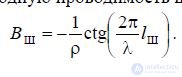

Fig. 2.5 - Coordination in the frequency band using one loop: a) matching device; b) graphs of the conductivity of the load and the loop
Thus, the selection of the magnitude of the wave resistance of the plume and its length can change the slope of the curve B Ш and the frequency band in which the reactive conductivity varies within acceptable limits.
The active component of the conductivity of the load, if necessary, can be coordinated using a quarter-wave transformer.
Step transformers are used to match the line with an active load or a load having a small reactive component. For example, matching when connecting two transmission lines with different wave impedances is achieved using an intermediate irregular line segment, called a transformer or a junction. Step transformers are a cascade connection of segments of transmission lines with different wave impedances, but having the same length. The wave resistances of adjacent steps differ by a small amount, and the reflections from them are small. The principle of operation of the step transformer is that at least a couple of steps will always be found, the reflection from which is compensated. The more steps, the better the matching and the wider the bandwidth. The structure of the transformer is determined by the number of steps n, the length of the step l i and the ratio of the characteristic impedances of the adjacent steps.
The properties of a transformer are described by its frequency response, which is the dependence of the operating attenuation L on frequency. Under the working attenuation understand the value
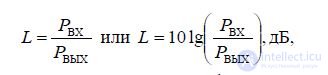
where P BX and P OUT are the power at the input and output of the transformer, respectively. Attenuation in a transformer is determined by reflections from its input in the frequency band. With this in
2
As an argument of the working attenuation function L, the quantity l is taken. Therefore, the frequency
The transformer characteristic is the dependence of the working attenuation L on the electrical length of the step.
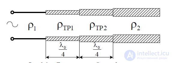
Fig. 2.6 - Two Stage Transformer
The characteristic impedance of the two-stage transformer segments (see Fig. 4.6) is determined by the relations:
In most cases, the determination of the structure of a transformer by a given frequency band of 2f and permissible mismatch KCBp is the task of synthesizing the device.
Smooth transitions are also used to coordinate active loads and can be considered as a limiting case of a step transition with an increase in the number of steps n to infinity and a constant transition length. The frequency characteristics of smooth transitions are non-periodic. The most frequently used *** in practice are the exponential transition, the Chebyshev transition, and the probabilistic transition, which is the limiting case of a step transition with a maximally flat characteristic.
A smooth transition is essentially an irregular two-wire transmission line, in which the running parameters and wave resistance are functions of the longitudinal coordinate (Fig. 2.7).

Fig. 2.7 - Smooth transition in the form of an exponential line
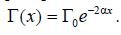
In this case, the equivalent circuit of an elementary segment of such a line of length dx has the form, as for a regular line (see Fig. 1.8). Therefore, the telegraph equations (1.8) remain valid. It can be shown that the characteristic impedance in such a line changes exponentially:
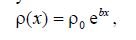
where 0 is the characteristic impedance at the beginning of the line; b is the coefficient determining
rate of change of wave resistance along the line. Choosing values 0 and b,
broadband matching can be provided. The effectiveness of matching depends on the rate of change of the wave resistance along the line. The slower the changes, the better the matching width and the longer the transition.
The disadvantage of smooth exponential transitions is their long length with
significant differences in wave resistance. For example, when  and admission
to mismatch  junction length
  . The length of the optimal
Chebyshev transition in 3 ... 4 times less.
Among smooth transitions with the same differences of wave resistance, lower boundary frequency and tolerance for mismatch, Chebyshev transitions have the shortest length.
A comparison of stepwise and smooth transitions shows that, with the same parameters, the length of the stepwise transition is noticeably less than that of a smooth one. However, the bandwidth of the smooth transition is much wider. With increased requirements for electrical accuracy, a smooth transition is preferable to a stepped one. The decrease in the electrical strength of the latter is explained by the concentration of the electromagnetic field at the junctions of individual steps.

Comments
To leave a comment
Microwave Devices and Antennas
Terms: Microwave Devices and Antennas