Lecture
Power amplifier on bpt
An amplifier is a device designed to amplify the voltage, current, and power of electrical signals.

Purpose of elements
The values of the resistances Rb, Rc, and the voltage of the source Ek determine the position of the operating point on the characteristics of the transistor in the rest mode (Ibp, Ubep, Ikp, Ukap).
Ek - for the introduction of the transistor in the amplifier mode.
Rk - to set the gain.
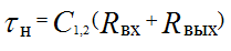
Capacitors C1 and C2 are used to separate the signal - they prevent the cascade from entering the input and the DC load component.
The main parameters of the amplifier
• voltage gain KU;
• input resistance Rvh;
• output resistance Rout;
• current gain KI
Analytical method of calculating the amplifier
Consider a substitution pattern

C1 and C2 are absent since Xc are small on alternating current.
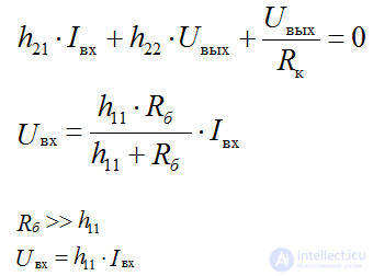
Let Rн → ∞, then according to the 1st Kirchhoff’s law for the node “k” we write the equations
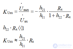
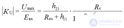
Gain
the sign "-" indicates that the input and output voltages are in antiphase)
Gain depends on the parameters of the transistor and the value of Rk
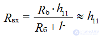
Input impedance
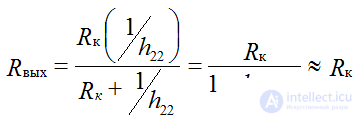
Output impedance
If we take into account the resistance of the load and the input source, the gain is equal to:
Graphic calculation of the amplifier
Construction of transient characteristics Ik = f (Ib)
1. Rest mode Uin = 0
We make the equation according to the Kirchhoff II law for a collector circuit
Uke = Ek-Rk Ik
According to this equation we build a direct load straight line “load line” - (IVC of resistor Rk)
Build a line at two points:
Mode xx: Ik = 0; Uke = Ek
Cs mode: Uke = 0; Ek = Rk Ik
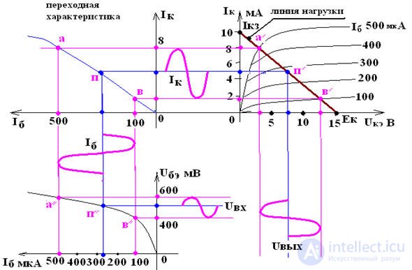
The intersection of the load lines with the output characteristics determine the collector current Ik and the collector-emitter voltage Uke, for any base current Ib.
RK is selected based on the required input gain, i.e. using Rk, set the gain of the amplifier, not forgetting the limitations: Uke max, Ik max, Pk max
Rк is usually 2-5 kOhm for low power transistors
Determine the rest point of the transistor:
Ucap ≈ Ek / 2 Ikp ≈ Ek / 2Rk
Ibp ≈ Ikp / h21
Up ≈ 0.3 V for Ge
Ubap ≈ 0,65 V for Si
The rest mode is provided by the resistance of the resistor Rb: according to the 2nd Kirchhoff's law for the input circuit Ube = Ek - Rb Ib
Rb = (Ek - Upe) / Ibp ≈ Ek / Ibp,
as Ek >> Ubap
On the transient response, a linear segment is selected; on it, the signal is transmitted from the input circuit to the output circuit without distortion.
2. Working mode
Uin ≠ 0
Uin = Rin iinhinin ≈ Ib => Ube = Ubep + uin this causes ripple of base current and collector current:
Ib = Ibp + ib and Ik = Ikp + ik
Output voltage ripple
Uкэ = Uкэп + uкэ Uвых = - Rк • iк
Capacitor C2 delays the DC component of the collector voltage and passes into the load device only the AC component uke, which is the output voltage of the amplifier.
If uin, ik, ib fit into the linear sections of the input and transient characteristics, then the shape of the output signal will be without distortion and correspond to the shape of the input signal.
Amplifier characteristics
Amplitude response of the amplifier AH

Straight line 0n linear part of the AH can be determined
Kyc = Uout / Uout
At hk, the amplitude response is non-linear, the gain factor Kyc decreases.
Amplitude Frequency Response
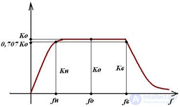
The frequency range where the gain is independent of frequency is called the bandwidth of the amplifier and is denoted by Δf.
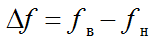
where fn is the lower frequency,
fv - upper frequency
Frequency properties of the amplifier
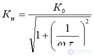
At ω <ωH large influence of reactance of coupling capacitors
XC1.2 = 1 / ωH С1,2, it becomes large and its influence is significant (C1,2 ~ 1 μF).
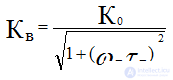
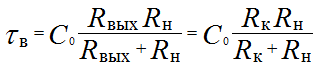
At ω> ω, the influence of C12 is small, but the element C0 begins to influence by shunting Rн and KU decreases.
The reduction in gain is estimated by the frequency distortion factor:
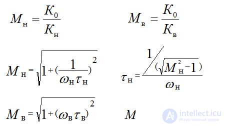
Quasiresonant frequency at which Ko is maximum


Comments
To leave a comment
Electronics, Microelectronics, Element Base
Terms: Electronics, Microelectronics, Element Base