Lecture
The basic rules of manual or automated execution of electrical circuits of products of all industries and energy facilities contains GOST 2.702-75. The rules for the implementation of electrical schematic diagrams (E3) were discussed in detail in Sec. 2, 3. The following are the basic rules for the execution of other types of schemes: structural, functional, connections, common, location and connection.
The electrical structural diagram defines the main functional parts of the product (device elements, functional groups), their purpose and connections. The construction of the scheme should give a visual representation of the interaction of all functional parts of the product.
All functional parts in the diagram are depicted in the form of rectangles or graphic symbols (Fig. 4.1) indicating the type of element / device and / or document (ESKD, GOST, TU or enterprise standard), on the basis of which this element / device is applied. The direction of the processes occurring in the product, indicate the arrows on the lines of their relationship.

Fig. 4.1. Block diagram of a direct gain receiver
In the case of a large number of functional parts, instead of names, types and symbols, it is allowed to place serial numbers to the right of the image or above them, as a rule, from top to bottom in the direction from left to right with their decoding in the table placed in the document. However, the use of ordinal numerals degrades the visibility of the scheme due to the fact that it is necessary to memorize the list of the table. To indicate the technical characteristics of the functional parts in the diagram, explanatory inscriptions, tables, diagrams of the form of currents and voltages, indications of parameters at characteristic points of the diagram (magnitudes of currents, voltages, mathematical dependencies) are placed.
The functional diagram depicts the functional parts of the product (elements, devices and functional groups) and the connections between them. For a complex product, several functional diagrams are developed explaining the processes taking place under the various intended modes of operation. The number of functional diagrams being developed for a product, the degree of their detailing and the volume of information to be placed are determined by the developer taking into account the features of the product. The graphical construction of the scheme should visually reflect the sequence of functional processes illustrated by the scheme. The actual location in the product elements and devices may not be considered.
The functional parts and the connections between them are depicted in the form of UGO set by the standards of ESKD (Fig. 4.2).

Fig. 4.2. dc amplifier circuit
Separate functional parts on the scheme are allowed to be represented as rectangles. In this case, parts of the circuit with element-wise detailing are depicted according to the rules of performing electrical schematic diagrams, and when enlarging the image of functional parts, according to the rules of performing structural diagrams (Fig. 4.3) with instructions in the document:
Names, types and designations of functional parts are recommended to be placed inside the rectangles. Abbreviated or conditional names should contain explanations in the fields of the scheme.
In fig. 4.3 according to the rules of performing electrical structural diagrams, the microphone amplifier A1 is shown, the master oscillator G1, the frequency multiplier U1, the power amplifier A2 with the antenna WA1, and the rules of the electrical circuit diagrams - the phase modulator module.

Fig. 4.3. Transmitter Functional Diagram
The connection diagram determines the constructive performance of the electrical connections of the elements in the product. The diagram shows all the devices and elements included in the product, their input and output elements (connectors, boards, clips, etc.) and the connections between them (wires, harnesses and cables).
Devices are depicted in the form of rectangles or simplified external outlines, elements - in the form of UGO, established in the standards of ESKD - rectangles or simplified external outlines. Inside rectangles or simplified external outlines depicting elements, it is allowed to place them in the UGO, and for devices - their structural, functional or schematic diagrams. Input and output elements are depicted in accordance with the CRB. The location of the images of input and output elements or pins inside the UHD devices and elements should approximately correspond to their actual positional location in the device or element.
It is allowed to place tables with characteristics of circuits and addresses of external connections instead of HGO input and output elements (Fig. 4.4).
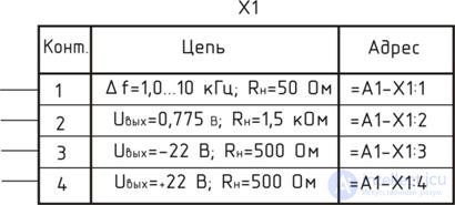
Fig. 4.4. Circuit table
The arrangement of graphic symbols of devices and elements in the diagram should correspond approximately to their actual placement in the product.
It is allowed on the diagram not to reflect the location of devices and elements in the product if the scheme is performed on several sheets or the placement of devices and elements at the place of operation is unknown.
Elements used in the product in part may be depicted incompletely on the diagram.
Near HGO devices and elements indicate the positional notation assigned to them on the schematic diagram. It is allowed to indicate its name and the type or designation of the document on the basis of which the device is used near or within the graphic designation of the device. In the absence of the concept of a product, reference designations to devices, as well as elements not included in the principle diagrams of the component parts of the product, are assigned in accordance with GOST 2.710-81 according to the rules given in paragraph 1.7.
It is not recommended to indicate on the diagram the designations of the conclusions (contacts) of the elements (devices) applied to the product or installed in the product documentation.
It is allowed to conditionally name the designations of the input and output elements with the placement of an explanation on the field of the circuit, if the design of the device / element and its documentation of the HBM are not specified. Wires, harnesses, cables on the diagram are assigned sequence numbers. Numbering is carried out within the product separately for cables and wires:
Through numbering of all wires and cores of cables within the product is allowed.
Wiring harnesses, cables and individual wires may not be marked if the product is included in the complex and designations are assigned within the entire complex. In this case, the corresponding explanation is placed on the scheme field.
If on the circuit diagram the electrical circuits are designated in accordance with GOST 2.709-89, then the same designations should be assigned to all single-conductor wires, cable conductors and wires of the harnesses. In this case, the harnesses and cables are numbered separately.
Numbers of wires and cable cores are affixed at both ends of their images. Cable numbers are stamped in circles placed in the discontinuities of cable images close to the branching points of the cores.
It is allowed not to show a circle with a large number of cables running in the same direction.
The harness numbers are put on the shelves of the callout lines near the branching points of the harness wires, the numbers of the wire groups are near the callout lines. With a large length on the scheme of wires, harnesses and cables are allowed to put down their numbers at intervals for easy reading of the scheme.
Devices with the same external connections on the diagram depict the connections for only one of them.
It is allowed not to show the connection of the wires of the cables to the input and output elements on the product diagram, if the devices have independent wiring diagrams. When depicting connectors, it is allowed not to depict individual contacts, but to replace them with tables indicating the connection of contacts (Fig. 4.5).
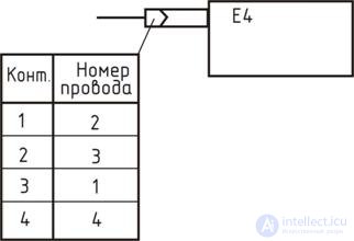
Fig. 4.5. Contact table
Tables can be placed near the connector image on the schematic field or on subsequent schematic sheets with assignment of reference designations of the respective connectors.
Allowed in the table to specify additional information, for example, data wires.
If a harness (a group of wires, a multicore cable) connects the same contacts of connectors, then a table is placed near one end of the image of the harness (cable).
On the wiring diagram of the product it is allowed to show its external connections.
Wires, groups of wires, harnesses and cables in the diagram show separate lines with a thickness of 0.4 to 1.0 mm.
Separate wires running in one direction are allowed to be merged into the group communication line, and when approaching the contacts, each wire and cable core should be shown again with a separate line.
It is allowed not to draw or break the lines depicting wires (groups of wires, harnesses and multicore cables) near the points of their connection to exclude multiple intersections.
In these cases, near the points of attachment (Fig. 4.6) or in the table on the free field of the scheme, the information necessary to ensure the uniqueness of the connection is placed.
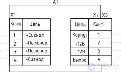
Fig. 4.6. Connection scheme
In complex circuits, when depicting multi-contact elements, lines depicting wiring harnesses (cables) are allowed, only bring the graphic designation of the element to the contour without showing connection to the contacts. Instructions on the connection of wires or cable cores to the contacts are performed in one of the following ways:

Fig. 4.7. Multi-contact image

Fig. 4.8. Image of a multi-contact element with a table
The introductory elements through which the wires pass are depicted in the form of UGO, established by ESKD standards. UGO of bushing insulators, sealed inlets, glands are shown in fig. 4.9.
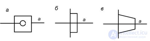
Fig. 4.9. UGO of the introductory elements: a - a bushing insulator; b - sealed lead-in; in - gland
It is allowed to indicate on the diagram by alphanumeric designation the functional belonging of wires, harnesses or cables to a specific complex, room or functional chain. Such a designation is placed before the designation of the wire with a hyphen or without it. The alphanumeric designation is included in the accepted designation of a wire, cable or cable.
Cable numbers are allowed to be inserted in a line break without a circle when assigning alphanumeric designations to cables.
The diagram indicates the brand and cross-section of wires, the number and cross-section of the cores of the cables and, if required, the colors of the wires. This data is placed near the lines depicting the wires and cables. In this case, the designation of wires and cables is not assigned.
If symbols are used for this, their decoding is placed on the schematic field. Information on the number of wires is placed in the rectangles to the right of the cable designation.
It is allowed to indicate in the scheme field the same brand, section and other data for all or most of the wires and cables. For harnesses, cables and wires manufactured according to the drawings, indicate the designation of the main design document.
With a large number of connections or in the absence of indications of the locations of the connections of wires and strands of a cable (cable), it is recommended to compile a table of connections in which the data on the wires, cables, cables and addresses of their connections are indicated. The table of compounds is placed on the first sheet of the diagram, or is carried out as an independent document with a large number of connections.
The table of compounds placed on the first sheet is located at a distance of not less than 12 mm from the main label, its continuation is to the left of the main label with the repetition of the table header.
The table of compounds in the form of an independent document is carried out on the A4 format (210 × 297) with the main inscription in accordance with GOST 2104-68 * in form 2 for the first sheet and in form 2a for the subsequent ones.
Recommended forms of the compound table are shown in Fig. 4.10.
In the columns of the table indicate the following data:
1) for a single wire - brand, section and, if required, colors;
2) for a cable recorded in the specification as a material, the brand, section and number of wires (these wires and cables are specified in accordance with the document on the basis of which they are applied;
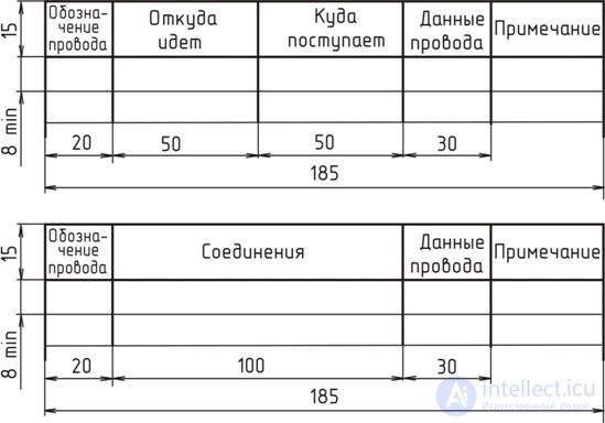
Fig. 4.10. The form of the tables of the list of connections of wires
When filling in the table of compounds, it is recommended to follow the following rules:
- when making connections with separate wires, they are recorded in the table in ascending order of numbers;
- when making wiring harnesses or wires and cables, before recording the wire of each cable or wires of each cable, a header should be placed, for example, “Wire 2”, “Cable 9” or “Cable ABVG.XXXXXX.13”;
- when making connections with individual wires, wiring harnesses and cables, the filling of the table should begin with the recording of individual wires without a header. Then wiring harnesses and cables are recorded with the appropriate headers.
The connection table is not compiled if the address of the connection is indicated at both ends in the images of individual wires, wiring harness and cable cores.
Above the title block it is allowed to place the necessary technical instructions:
This type of circuit shows the external connections of the product. The diagram displays the product image, its input and output elements (connectors, clips, etc.) and the ends of wires and cables of external mounting supplied to them, about which the data on the connection of the product (characteristics of external circuits, addresses) are placed.
In the diagram, the products and their constituent parts are depicted as rectangles, and the input and output elements (connectors) are depicted as UGO.
It is allowed to depict products and input / output elements in the form of simplified outlines.
The input and output elements inside the graphic designation of the product are placed in accordance with their actual location in the product and indicate their reference designation assigned to them on the circuit diagram of the product.
Introductory elements (glands, sealed inlets, bushing insulators), through which wires or cables pass, are depicted in the form of UGO, as well as in the connection diagrams (see Fig. 4.9).
It is recommended to indicate on the scheme the designations of input, output or output elements applied to the product. If the designations of these elements in the product design are not specified, it is allowed to conditionally assign them designations in the diagram. The assigned designations are repeated in the corresponding design documentation, placing the necessary explanations in the scheme field.
It is permitted for CSO connectors to indicate their names or designations of documents on the basis of which they are applied.
The wires and cables in the diagram show separate lines.
On the scheme it is allowed to indicate the brands and cross sections of wires, their colors, cable marks, the number and occupancy of the wires, their cross sections. If symbols are used for this, they must be deciphered on the scheme field.
The diagram shows the devices and elements included in the complex, as well as the wires connecting them, wiring harnesses and cables. Devices and elements depicted in the form of rectangles.
Допускается изображать элементы в виде УГО или упрощенных внешних очертаний, а устройства – в виде упрощенных внешних очертаний. Расположение графических обозначений на схеме должно примерно соответствовать действительному расположению устройств и элементов в изделии.
Если действительное размещение устройств и их элементов неизвестно, то графические обозначения устройств и элементов располагают с учетом простоты и наглядности изображения электрических соединений между ними.
Около изображения каждого устройства и элемента показывают его наименование, тип или обозначение документа, на основании которого они приведены.
В случае большого количества устройств и элементов их соединения записывают в перечень элементов с присвоением позиционных обозначений, которые проставляют рядом с графическими обозначениями.
Устройства и элементы, сгруппированные в посты или помещения, рекомендуется записывать по постам или помещениям.
Входные, выходные и вводные элементы изображают на схеме в виде УГО, установленных в стандартах ЕСКД с учетом их действительного расположения внутри устройств.
Допускается не учитывать действительное размещение элементов в изделии, если оно снижает наглядность изображения электрических соединений в сложных схемах, а заменять его соответствующим пояснением на поле схемы.
Проходные изоляторы, гермовводы, сальники изображают в виде УГО, как и на схемах соединений (см. рис. 4.9).
Разрешается взамен УГО входных и выходных элементов помещать таблицы с указанием подключения контактов (см. рис. 4.5), как и в схемах соединений.
На схеме указывают обозначения входных, выходных и вводных элементов, нанесенные на изделие. Если в конструкции изделия обозначения элементов не указаны, то им условно присваивают обозначения на схеме, повторяя их в соответствующей конструкторской документации. При этом на поле схемы помещают необходимые пояснения.
Допускается размещать обозначения документов соединителей с простановкой количества контактов на полках линий-выносок.
Провода жгуты и кабели показывают отдельными линиями и обозначают порядковыми номерами в пределах изделия. Разрешается сквозная нумерация в пределах жгута, кабеля, если провода, входящие в жгуты, пронумерованы в пределах каждого жгута, кабеля. Номера проводов проставляют около концов их изображений. Короткие соединители допускается нумеровать около середины изображения.
Номера кабелей проставляют в окружностях, помещенных в разрывах их изображений, а номера жгутов – на полках линий-выносок.
Если на схеме принципиальной электрическим цепям присвоены обозначения в соответствии с ГОСТ 2.709-89, то одножильным проводам, жилам кабелей и проводам жгутов присваивают те же обозначения, что и в схемах соединений.
На схеме изделия, в состав которого входит несколько комплексов, одножильные провода, кабели и жгуты нумеруют в пределах каждого комплекса. В этом случае буквенно-цифровое обозначение, устанавливающее принадлежность их к определенному комплексу (функциональной цепи), проставляют перед номером через знак дефис. Обозначение кабеля при этом в окружности не вписывают.
Около изображений одножильных проводов и кабелей указывают марку, сечение, количество жил кабеля, иногда расцветку, а для проводов, кабелей и жгутов, изготовленных по чертежам, – обозначение основного конструкторского документа.
При большом количестве соединений эти сведения рекомендуется записывать в перечень. Форма таблицы перечня проводов, жгутов и кабелей приведена на рис. 4.11.

Fig. 4.11. Форма таблицы перечня жгутов и кабелей
Перечень помещают на первом листе схемы или выполняют в виде последующих листов. На первом листе схемы перечень рекомендуется располагать над основной надписью на расстоянии от нее не менее 12 мм.
In the columns of the list indicate the following data:
Допускается не вносить в перечень кабели, прокладываемые при монтаже изделия.
Общую схему рекомендуется выполнять на одном листе. Если схема сложная, и её невозможно разместить на одном листе, то на первом листе вычерчивают изделие в целом, изображая посты и помещения контурами очертаний со связями между ними. Внутри очертаний постов и помещений изображают только те устройства и элементы, к которым подводят провода и кабели, соединяющие посты или помещения.
На последующих листах вычерчивают схемы отдельных постов или помещений. Если в состав изделия входит несколько комплексов, то общую схему каждого комплекса выполняют на отдельном листе.
Схема расположения определяет относительное расположение составных частей изделия, а при необходимости, также жгутов, проводов, кабелей (рис. 4.12). На схеме изображают составные части изделия и при необходимости связи между ними, а также конструкцию, помещение или местность, на которой эти части расположены. Составные части изделия изображают в виде упрощенных внешних очертаний и/или УГО, которые располагают в соответствии с действительным размещением частей изделия в конструкции или на местности.
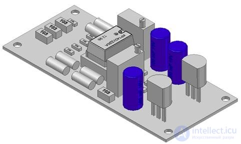
Fig. 4.12. 3D-модель расположения компонентов
Провода, жгуты и кабели изображают в виде отдельных линий или упрощенных внешних очертаний.
Around images of devices and elements are placed their name and types and / or designation of the document on the basis of which they are applied.
With a large number of components of the product, this information is placed in the list of elements with the assignment of reference designations in accordance with the conceptual diagram. Layouts can be made on sections of structures, sections or plans of buildings and on their visual images. In the automated implementation of the layout of the three-dimensional model of the product and its component parts is preferred.
1. Enter the alphanumeric code of the electrical structural circuit.
2. Specify the alphanumeric code of the electrical functional circuit.
3. Enter the alphanumeric code of the electrical circuit.
4. Specify the alphanumeric code of the wiring diagram.
5. Укажите буквенно-цифровой код схемы электрической общей.
6. Укажите буквенно-цифровой код схемы расположения.
7. Для какой схемы предпочтительно использование 3D модели?
8. Какую схему рекомендуется выполнять на одном листе?
9. Какая схема может выполняться в виде самостоятельного документа на форматах А4?
10. Что входит в состав схемы электрической структурной?
11. В чем отличие схемы электрической структурной от схемы электрической функциональной?
12. В чем отличие схемы электрической подключения от схемы электрической соединений?
13. Укажите буквенно-цифровой код схемы электрической принципиальной.

Comments
To leave a comment
Electronics, Microelectronics, Element Base
Terms: Electronics, Microelectronics, Element Base