Lecture
Parametric voltage regulator
In many radio-electronic devices, where secondary power supply sources are used, the requirements to maintain the voltage or current at a certain constant level are required, regardless of possible changes in the input voltage and output current. To achieve this, voltage or current stabilizers are used. In this educational-methodical manual we consider a parametric voltage stabilizer on a semiconductor zener diode. Parametric stabilizers have a simple design and high reliability, but have low efficiency.
Diagram of parametric voltage regulator fig. 4 consists of a ballast resistor Rbal (to limit the current through the Zener diode), and a Zener diode connected in parallel to the load, performing the main function of stabilization. 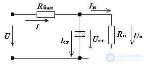
Fig. 4 Parametric parametric voltage regulator
The basic ratios of currents and voltages in the stabilizer are determined by the first and second Kirchhoff laws: 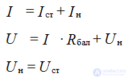
The principle of operation of the parametric stabilizer
The principle of operation of the parametric dc voltage stabilizer is conveniently explained using fig. 5, which shows the volt-ampere characteristic (IVC) of the Zener diode and the “inverted” IVC of the ballast resistor. The work of the voltage regulator is as follows. When you change the voltage at the input of the stabilizer U, there is a corresponding change in current I, and, consequently, the currents of the Zener diode and the load change. However, when the current of the Zener diode changes, the voltage on it will change by a very small amount in accordance with the current-voltage characteristic of the Zener diode (Fig. 5), i.e. almost unchanged. According to the second Kirchhoff's law, when the input voltage changes, the voltage drop on the ballast resistance changes in proportion to the current, is equal to the input voltage increment. In other words, all the increment of the input voltage drops on the ballast resistance, and the voltage on the Zener diode and on the load almost does not change. We write the above mathematically:
U ± ∆U = (Ist + In ± ∆Ist) • Rbal + Un
Taking, U = const and Rn = const, we get In = const, while the condition for maintaining the working point of the zener diode in the section AB of the current-voltage characteristic (Fig. 5) is determined by the formula:
± ∆U = ± ∆IstRbal 
Fig. 5. Explanation of the principle of the voltage regulator
From this it follows that the normal operation be ensured by the appropriate choice of the magnitude of the ballast resistance. Then, when the voltage changes at the input of the stabilizer, the normal stabilization limits of the output voltage Un are not violated.
When voltage is stabilized by taking, In = var and Rn = var and U = const, currents are redistributed at the input of the stabilizer between the load and the zener diode while maintaining the same voltage at the zener diode and the voltage drop at the ballast resistance according to the equation:
U = I • Rbal + Un = ((In ± ∆In) + (Iast ± ∆Ist)) • Rbal + Un
For normal operation of the stabilizer, with varying loads, a change in current should not lead to the output of the current of the Zener diode beyond its maximum and minimum allowable values.
Provided that U = const and Rh = const, the stabilizer’s calculation is reduced to choosing a zener diode and choosing Rbal, then from the system of equations (1) we get the formula for calculating Rbal: 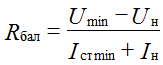
The resistance of the resistor should be such that the current of the Zener diode is at least Ist min, i.e. did not go beyond the working area AB (fig.5) of the current – voltage characteristic of the zener diode.
The ballast resistance determines the main losses of the stabilizer, therefore parametric stabilizers are used only in low-power circuits.
Zener diode is selected by parameters from the directory:
1. Ist max - the maximum permissible current of the zener diode;
2. Ust - voltage stabilization;
3. Ist min - the minimum current of the zener diode.
The main parameters of the stabilizer:
1. Stabilization factor equal to the ratio of input and output voltage increments. The stabilization factor characterizes the quality of the stabilizer. 
2. Output impedance stabilizer
Rout = Rdiff
To find the Kst and Rout, the stabilizer replacement scheme for increments of Fig.6 is considered. The nonlinear element operates on the stabilization section, where its resistance to alternating current Rdif is a parameter of the stabilizer. 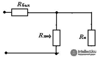
Fig. 6 Equivalent circuit of parametric voltage regulator
Differential resistance Rdif is determined from the equation: 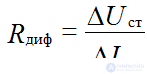
For the equivalent circuit, we obtain the stabilization factor taking into account that Rn >> Rdif and Rbal >> Rdif: 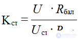
Stabilization factor of parametric voltage regulator Кст = 5 ÷ 30
To obtain an increase in the stabilized voltage, a series connection of zener diodes is used.
Parallel inclusion of zener diodes is not allowed. In order to increase the stabilization factor, it is possible to cascade several parametric voltage regulators

Comments
To leave a comment
Electronics, Microelectronics, Element Base
Terms: Electronics, Microelectronics, Element Base