Lecture
DC amplifiers
When measuring, in electronic devices it is necessary to amplify signals of very low frequencies (fractions of Hz). DC amplifiers are designed to amplify signals that slowly vary over time, that is, signals f → 0.

Figure 1 amplitude-frequency response of the DC amplifier
Uout is determined by the amplified useful signal and a false signal generated by changing over time the parameters of the cascade mode for direct current.
Zero drift
A spontaneous change in the Uout dc amplifiers with a constant Uin = const is called zero drift.
• Udr = DUvyhdr / KU;
• KU - amplifier gain,
• Udr - false input signal.
TFC scheme
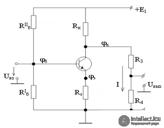
Figure 2 DC Amplifier
DC amplifier Fig 2, with two power sources + E1 and -E2, which create a positive and negative voltage relative to a common point (having zero potential).
UR3 + UR4 = jk + E2 is applied to the divider R3 - R4, the potential of the midpoint of the divider must be equal to zero, then Uout = 0, therefore, UR3 = jk, UR4 = E2.
Uvh >> Udr for normal operation.
In order not to violate the mode of operation of the transistor, a current I = (0.02¸0.1) Ik should flow through the divider; I £ Ik.
R3 = UR3 / I; R4 = UR4 / I
The divider at the output of the DC amplifier compensates the DC component of the collector voltage, but with some decrease transmits the amplified voltage from the collector of the transistor to the output of the amplifier.
K = Ko • R4 / (R3 + R4);
Ko - gain without divider. In practice, Ko decreases by 1.5 - 2 times.
To combat drift zero apply:
• voltage stabilization of power supplies;
• stabilization of temperature;
• DC differential amplifiers.

Comments
To leave a comment
Electronics, Microelectronics, Element Base
Terms: Electronics, Microelectronics, Element Base