Lecture
2.1. General use symbols (GOST 2.721-74)
2.2. Resistors (GOST 2.728-74)
2.3. Capacitors (GOST 2.728-74)
2.4. Inductors, chokes and transformers (GOST 2.723-69)
2.5. Switching devices (GOST 2.755-74, GOST 2.756-76)
2.6. Semiconductor devices (GOST 2.7Z0-73)
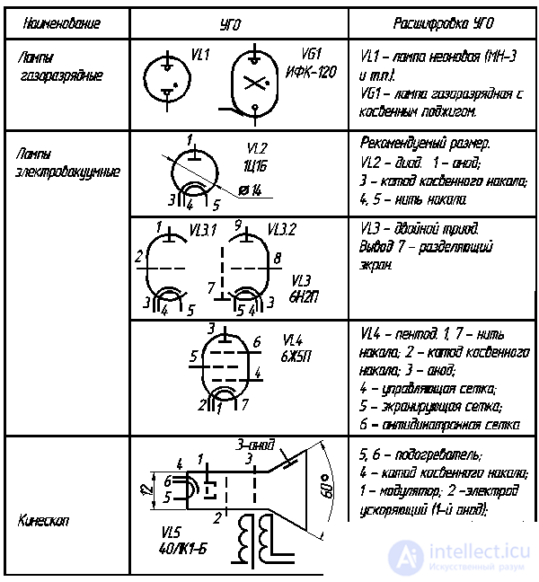
2.7. Electrovacuum devices (GOST 2.731-81)
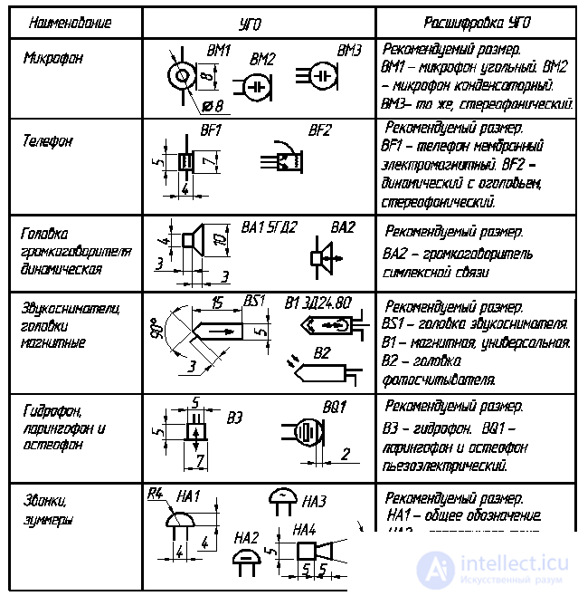
2.8. Electro-acoustic devices (GOST 2.741-68 *)
2.9. Piezoelectric devices, measuring devices, power sources (GOST 2.736-68, GOST 2.729-68, GOST 2.742-68, GOST 2.727-68)
2.10. Electrical machines (GOST 2.722-68 *)
Questions for self-test
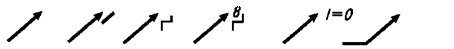
To build a CSB with the refinement of the features of the elements of the schemes, use basic symbols and various signs. Regulation signs — various arrows crossing the source symbol or included in it, crossing the source symbol at an angle of 45 °, indicating a variable parameter of the circuit element (Fig. 2.1, a ) have a wide distribution in the circuits of radio devices and electrical products .
The arrow can be supplemented with a digit symbol. So, on fig. 2.1, b , c , d shows the nature of regulation: linear, stepped, 8-step. In fig. 2.1, d arrow supplemented by the condition of regulation. Arrow with a break in fig. 2.1, e , g , and and the inscription indicate that the regulation parameter varies according to a certain law. Arrows in fig. 2.1, k , l, m indicate trimming regulation. In the upper part of the arrow, there may be a symbol indicating the location of the regulating element in this product: on the front panel, rear panel or inside. Symbols of general use make up signs indicating the direction of movement: mechanical movements, magnetic, light fluxes, etc.
|
a B C D E F |
|
|
|
OK and to l m |
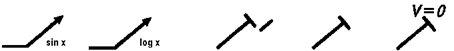 |
Fig. 2.1. Regulation Signs
In fig. 2.2 shows the designations of rotational (Fig. 2.2, a ), swinging (Fig. 2.2, b ), complex (Fig. 2.2, c ) movements, direction of perception of the magnetic signal (Fig. 2.2, d ) and light flux (Fig. 2.2, d ).
a B C D E


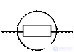
Fig. 2.2. Direction signs
Part of the symbols of some elements is a sign indicating the method of controlling the moving elements of the circuit. In fig. 2.3 shows the designation of manual pressing (Fig. 2.3, a ) or drawing out (Fig. 2.3, b ), turning (Fig. 2.3, c ), foot drive (Fig. 2.3, d ) and fixing the movement (Fig. 2.3, d ) .
a B C D E


Fig. 2.3. Signs indicating control method
HBO elements of electrical circuits are allocated in groups and tabulated for better perception. The tables give the recommended sizes of UGOs for the execution of radio devices and electrical products. When making drawings — posters — in course and degree design, reference should be made to the literature [2], in which HBO structures are shown for the main figures A and B, showing the proportional relations of the elements.
The main purpose of resistors is to provide active resistance in the electrical circuit. The resistor parameter is the resistance, which is measured in ohms, kilo-ohms (1000 ohms) and megohms (1000000 ohms).
Resistors are divided into fixed, variable, trimming and nonlinear (table. 2.1). According to the method of execution, wire and non-wire (metal-film) resistors are distinguished.
The alphanumeric reference designation of resistors consists of the Latin letter R and the sequence number according to the scheme.
Table 2.1
UGO resistors

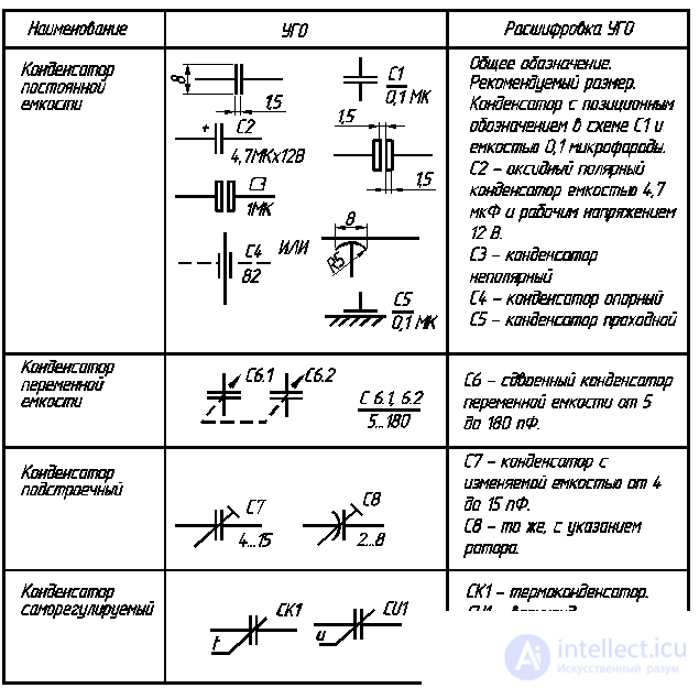
Capacitors are radio elements with a concentrated electrical capacitance formed by two or more electrodes separated by a dielectric. There are capacitors of constant capacity, variable (adjustable) and self-regulating. Constant capacitors of high capacity are often oxide, and, as a rule, have a polarity connected to an electrical circuit. Their capacitance is measured in farads, for example, 1 pF (picofarad) = 10 –12 F, 1 nF (nanofarad) = 10 -9 F, 1 µF (microfarad) = 10 -6 F (Table 2.2). The alphanumeric reference designation of capacitors consists of the Latin letter C and the sequence number according to the scheme.
Table 2.2
UGO capacitors
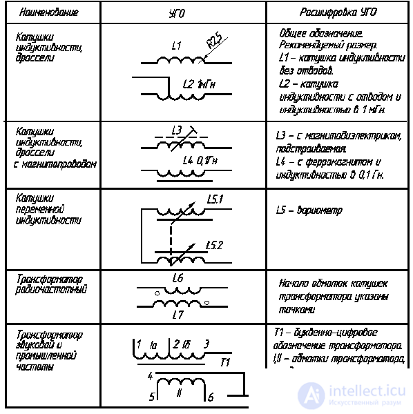
The alphanumeric reference designation of inductors and chokes consists of the Latin letter L and the sequence number according to the scheme. If necessary, indicate the main parameter of these products - inductance, measured in Henry (HH), milligenres (1 mH = 10 -3 H) and microgens (1 μH = 10 -6 H). If the coil or choke has a magnetic core, the UGO is supplemented with its symbol - a dashed or solid line. RF transformers can be with or without magnetic conductors and have the designation L1, L2, etc. Transformers operating in a wide frequency band are designated by the letter T, and their windings are in Roman numerals (Table 2.3).
Table 2.3
UGO induction coils and transformers
CSD switching devices - switches, switches, electromagnetic relays - are built on the basis of contact symbols: closing, opening and switching (table 2.4). The standard provides for the reflection of design features in the UGO of such devices: non-simultaneous operation of contacts in a group; absence (presence) of fixation in one of the positions; switching device control method; functional purpose.
Table 2.4
CSO switching devices
The end of the table. 2.4


2.6.1. Diodes, thyristors, optocouplers
The diode is the simplest semiconductor device with one-way conductivity due to the electron-hole transition
(p – n-junction, see table 2.5).
Table 2.5
UGO semiconductor devices

In the UGO diodes - tunnel, reversed and Schottky diodes - additional strokes to the cathodes are introduced. The property of reverse-biased p – n-transition itself as the capacitance used in special varicap diodes. A more complex semiconductor device is a thyristor , having, as a rule, three p – n junctions. Typically, thyristors are used as switching diodes. Thyristors with leads from the outermost layers of the structure are called dinistors . Thyristors with an additional third output (from the inner layer of the structure) are called triristors . HLT of a symmetric (bidirectional) trinistor is obtained from the symbol of a symmetric dinistor by adding a third pin.
A large group consists of semiconductor devices - photodiodes , LEDs and LED indicators . It is especially necessary to dwell on optocouplers - products based on the joint operation of light-emitting and light-receiving semiconductor devices. The group of optocouplers is constantly replenished.
A large replenishment occurs in the group of field-effect transistors, the conditional graphic symbols of which are not yet noted in the national standards.
2.6.2. Transistors
Transistors are semiconductor devices designed to amplify, generate, and transform electrical circuits ***.
A large group of these devices consists of bipolar transistors having two p – n junctions: one of them connects the base with the emitter (emitter junction), the other with a collector (junction collector junction).
The transistor, the base of which has a conductivity of type n, is designated by the formula p – n – p, and the transistor with a base of type p has the structure n – p – n (Table 2.6). Several emitter regions have transistors included in integrated assemblies. It is allowed to depict transistors according to GOST 2.730-73 without a housing symbol for unpackaged transistors and transistor arrays.
Table 2.6
Corm transistors

The end of the table. 2.6

Electrovacuum devices are devices whose action is based on the use of electrical phenomena in a vacuum. The UGO system of these devices is built in an elementwise fashion. The designations of the balloon, filament (heater), mesh, anode, etc. are taken as the basic elements. The balloon is sealed and can be glass, metal, ceramic, metal-ceramic. The presence of gas in the cylinder in gas-discharge devices is indicated by a dot inside the symbol (Table 2.7).
Table 2.7
UGO electrovacuum devices
Electroacoustic devices are devices that convert the energy of sound or mechanical trains to electric and vice versa. The main letter code (except for alarm devices) is the Latin letter B.
Table 2.8
UGO electroacoustic devices
In radio electronic equipment (REA), devices are widely used, whose action is based on the so-called piezoelectric effect (piezo). There is a direct piezoelectric effect, when electric charges arise on the surface of the body, subjected to deformation, and inverse. The use of resonators in electronic equipment is based on the use of direct piezoelectric effect. The letter code of piezoelectric elements and resonators is the Latin letters ВQ. On the basis of piezoelectric resonators, various bandpass filters are made (letter code Z and ZQ) . Piezo elements are widely used in piezoelectric transducers (subsection 2.8). Piezoelectric transducers are also used in ultrasonic delay lines. The standard is not set the letter code of these devices, it is recommended to designate the Latin letter E.
To control the electrical and non-electrical quantities in the technique, various devices are used, their letter code is the Latin letter P, and the total UHT of the instruments is a circle with two differently directed lines — leads.
For autonomous power supply of REA, electrochemical current sources are used - galvanic cells and batteries (code - letter G).
For protection against overcurrent and short circuits in the load
in devices with mains supply fuses are used (Table 2.9). The code of such products is the Latin letter F.
Table 2.9
CSO devices, devices, power supplies

The end of the table. 2.9


In devices of automation and telemechanics, in the construction of industrial machines and road-building machines, electric machines are used to drive various mechanisms. The basic designation of the stator and rotor of an electric motor has the shape of a circle (Table 2.10).
Table 2.10
Basic elements of UGO electric machines

GOST 2.722-68 * provides for UGO, explaining the design of electric machines (Table 2.11), UGO electric machines in two forms (Table 2.12). Inside the circle it is allowed to indicate the following inscriptions in Latin letters: G - generator; M - the engine; B - pathogen; ВR - tachogenerator. It is also allowed to indicate the type of current, the number of phases, the type of connection of the windings.
Table 2.11
UGO, explaining the design of electrical machines (GOST 2.722-68 * )

Table 2.12
UGO electrical machines (form 1 and 2)

1. List the types of signs of general application on the schemes.
2. Name the letter code for designating resistors.
3. Name the letter code for identifying capacitors.
4. Name the letter code for the designation of inductors.
5. Name the letter code for designation of power frequency transformers.
6. Name the letter code designation of the relay.
7. Name the letter code for the designation of thyristors.
8. Name the letter code designation of the diodes.
9. What is the letter code for the designation of transistors?
10. Name the letter code designation calls, buzzers and hydrophones.
11. Name the letter code designation of analog measuring instruments.
12. List the letter codes of electric cars.
13. Convert the value of 100 nF to microfarads (μF).
14. Specify the recommended size of the UGO resistors.
15. Specify the recommended size of the UGO transistors.

Comments
To leave a comment
Electronics, Microelectronics, Element Base
Terms: Electronics, Microelectronics, Element Base