Lecture
Operational amplifiers
An operational amplifier (hereinafter OU, amplifier) is an analog electronic micro-device with a differential input designed to amplify and generate electrical signals, implement mathematical operations in analog form, create electric filters and threshold devices, i.e. to perform various operations with electrical signals.
Internal op amp device
The internal device of the operational amplifier is shown in Fig. 5. The input unit is a differential amplifier (DU), which may consist of 3-4 stages. To create a large internal gain, a voltage amplifier block (VL) is used. As the output unit is usually used power amplifier (PA), made by a transformerless circuit.
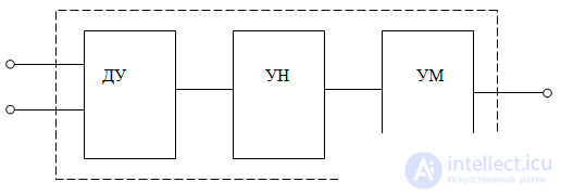
Figure 5. The block diagram of the operational amplifier
OU has two inputs and one output. One of the inputs of the OS is called inverting, since when voltage is applied to it, its sign at the output becomes opposite. The other input is called non-inverting: when voltage is applied to it, its sign at the output does not change. This state of the OU is possible due to the power supply from two voltage sources with different signs. As a result, under certain conditions, the output block of the op-amp has a virtual zero potential, with respect to which the sign of the potential (voltage at the output) may vary in one direction or another with respect to the common output. As in any amplifier device, the op amp can be covered by feedback (OS)
Op amp Parameters
OU, depending on the mode of operation, is characterized by either static or dynamic parameters.
The main statically parameters of the OS include:
1. Gain Ko. Its value may be 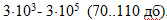
2. Unit frequency band f1 - upper frequency at which the gain falls to unity. The value of f1 at a number of OU reaches  Hz
Hz
3. The zero bias voltage UCM is the potential difference between the inverting and non-inverting inputs, which must be applied so that the output voltage is zero. This potential difference from operational amplifiers is 0.001-10 mV, depending on their quality.
4. Input bias currents  - currents of non-inverting input and inverting input, respectively, when they are grounded. The magnitude of these currents is of the order of a few thousandths of a microampere. Modern OU can have this parameter
  BUT.
BUT.
5. Average input bias current  - half the amount of input bias currents.
6. Differential input bias current  - the difference between the modules of the input bias currents.
The main dynamic parameters of the OS include:
7. The slew rate of the output voltage  - the ratio of the voltage increment at the output of the shelter to the time interval over which this increment is observed. The value of this parameter is 0.1-100 V / µs.
8. The coefficient of attenuation of common-mode input voltages XF - the ratio of the increment of common-mode input voltages to the input voltage, causing the same increment of the output voltage. Modern OU have XF = 70-120 dB.
In operational amplifiers, the input stage is performed in a differential circuit with a single-phase output.
Conventional symbols of the OS
Conditional graphic symbols (VGO) of the operational amplifier (OU) are shown in Fig. 6.
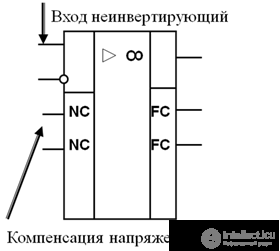
Figure 6, but presented complete
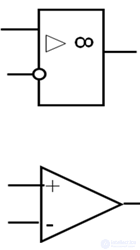
Figure 6, b - simplified designation of OU.
The inputs are on the left, the outputs are on the right. Terminals intended for connecting the power supply (+ U, -U), offset voltage compensation (NC) and frequency correction (FC) circuits are depicted in areas of additional fields on either side of the HLF.
For the convenience of analyzing the principle of operation of the OS in various schemes use the concept of an ideal OS. Ideal OU is called OU, which has a differential voltage at the inputs  always maintained equal to zero automatically by the op-amp itself in the presence of an operating circuit on the inverting input (this is true when Ucm = 0), the input current
 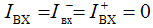 bandwidth at unit gain
  , output resistance is zero, Rout = 0.
From the given properties of the parameters of an ideal OU, it follows that the potentials of the inverting  and non-inverting
  inputs are equal to:
  , and the current through the input elements is equal to the current in the feedback circuit.
Uout = (Uin1-Uin2) ∙ Kou the difference voltage is called the differential input signal. This is the voltage that is applied between the inverting and non-inverting inputs.
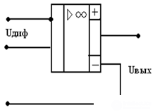
Figure 7 Diagram of the definition of the differential voltage.
• If both inputs of an op-amp are connected together, then the resulting circuit in Fig. 8 will have only one input, and the voltage applied to it is called common-mode Usf = Uin 1 = Uin 2.
• For common mode, output voltage should be zero
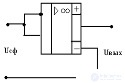
Figure 8 Common-Mode Voltage Detection Circuit
Characteristics of the Operational Amplifier

OU Parameters
Static:
- Gain
- Input impedance
- Output impedance
- EMF offset
Common mode rejection ratio
Dynamic:
1. Cutoff frequency fср - the value of this frequency corresponds to √2 times the decrease in the magnitude of the gain coefficient of an op-amp (3dB)
fср - is the OU bandwidth.
2. The frequency of the unit gain f1 - at which Coe is reduced to 1. For modern op amps
f1 = 10,000 ÷ 10,000,000 Hz.
3. The maximum slew rate of the output voltage Uout ~ 0.1 ÷ 100 V / µs.
4. Settling time tust.
The main parameters of an ideal op amp
• Differential gain factor Kdiff → ∞
• Common mode gain Xenf = 0
• Input impedance Rin → ∞
(input currents are 0)
• Output impedance Rout = 0
OU classification
• universal or general purpose (K140UD7) K = 1000 ... 100000, Esm = 4mV, f1 = 0.8 MHz
• precision or instrumental (K140UD24) K = 1,000,000, Esm = 5 μV, f1 = 2 MHz
• high-speed (154UD2) K = 10,000, Ecm = 2 mV, f1 = 50 MHz
• micropower (К1423УД1) К = 10000, Есм = 5мВ, f1 = 1,5МГ

Comments
To leave a comment
Electronics, Microelectronics, Element Base
Terms: Electronics, Microelectronics, Element Base