Lecture
Electrical signal generators
An electronic generator is a device that converts the energy of a dc source to the energy of electromagnetic coils of various shapes, required frequency and power.
There are electronic generators of harmonic coli *** s (sinusoidal) and pulsed (relaxation) col s ***.
Generator classification
Depending on the frequency, the generators are divided into three types:
1. low frequency
2. high frequency
3. super frequency
Depending on the type of excitation generators are divided:
1. with independent arousal
2. with self-excitation (auto-generators)
There are several modes of operation of generators:
1. avtokol *** ***
2. waiting
3. synchronized
Structural diagram of the generator 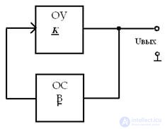
self-excitation conditions 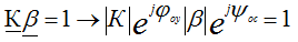
• two conditions that must be met simultaneously:
1. amplitude balance condition 
2. phase balance condition (only at resonant frequency) 
• To obtain stationary stable kole *** in the oscillator must meet the condition: 
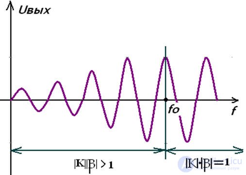
High frequency generator 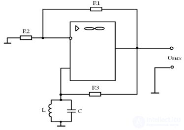
• the self-excitation condition is used - the condition of the balance of amplitudes and phases at the resonant frequency, R3 >> Roc 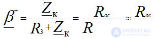
• In order for the tracks to be slightly larger in amplitude, the condition 
Low frequency generator 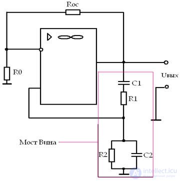
• An op-amp with a negative feedback link on Ro Roc, specifying the gain factor K = 3.
• Wien Bridge - a link of positive feedback on R1C1 and R2C2; have a transmission coefficient
β = 1/3 and ψ = 0, with R1 = R2 = R, C1 = C2 = C
• Oscillator frequency: 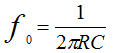
To adjust the frequency, either R1 and R2 (stepless adjustment) or C1 and C2 on the switches are changed. The output will be a pure sine wave, if you put a posistor or an incandescent lamp in the OOS circuit (the current increases the resistance). 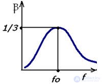
Options
• frequency f
Sine wave cola generators *** hold frequency better than other waveform generators. 
The goal is to improve this parameter, i.e. reduce to zero
Generator application
• as an integral part of measuring instruments and automatic systems
• to power the instruments for monitoring the composition and quality of various substances
• for powering installations for high-frequency heating of metals, etc.
• Sound generators and high-frequency generators in radio engineering and electronics.
Impulse generators
Electronic keys 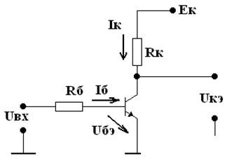
• The key is “open” - the transistor operates in the cut-off mode, i.e. through the transistor flows the minimum current ik = 0, Uke = Ek. The resistance of the transistor is very large - open.
• The key is “closed” - the transistor operates in the saturation mode: Uke = 0, the current is limited by the resistor Rc - the transistor enters the saturation mode under the condition that the resistance of the transistor is equal to zero in this mode.
• When a transistor switch is operated, switching from an open state to a closed one and vice versa occurs abruptly, while the power losses are insignificant.
Pulse mode of the device - this short-term signal exposure alternates with a pause.
Pulses of the form:
• Rectangular
• Triangular
• Sawtooth
• Exponential, etc.
The most common pulse shape is rectangular.
Pulse parameters:
Pulse period Ti or frequency fi = 1 / Ti
Pulse amplitude u and
Pulse duration t and
Front duration tf
Cut duration tc
Pause duration tп

Comments
To leave a comment
Electronics, Microelectronics, Element Base
Terms: Electronics, Microelectronics, Element Base