Lecture
Relay (fr. Relais ) - an electrical or electronic device (key), designed to close and open different parts of electrical circuits with given changes in electrical or non-electrical input effects.
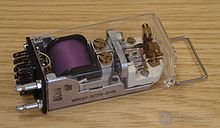
Usually, this term refers to an electromagnetic relay - an electromechanical device that closes and / or opens mechanical electrical contacts when an electrical current is applied to the winding of the relay, which generates a magnetic field that causes the ferromagnetic armature to move the relay connected mechanically to the contacts and the subsequent movement of the contacts commutes the external electrical circuit .
Often, relays are also called a variety of devices, closing or opening contacts when changing some, not necessarily an electrical value. These are, for example, devices sensitive to temperature (thermal relays), illuminance (photo relay), sound pressure level (acoustic relays), etc. Also, various relays are often referred to as relays, for example, a car's turn indicator timer, on / off timers of various devices and devices, such as home appliances (timers).
There is a class of electronic solid-state semiconductor devices called optorele ( solid-state relay ), these devices are not considered in this article.
The main parts of the electromagnetic relay are: electromagnet, anchor and switch. An electromagnet is an electrical wire wound on a coil with a core of magnetic material. Anchor - a plate made of magnetic material, through a pusher that controls the contacts.
The first relay was invented by the American Joseph Henry in 1831 and was based on the electromagnetic principle of operation. It should be noted that the relay J. Henry was not switching. The word relay originated from the English relay, which meant changing tired post horses at stations or transmitting a relay (relay) to a tired athlete. As an independent device, the relay was first mentioned in the patent for the telegraph of Samuel Morse.
In the diagrams, the relay is indicated as follows:


1 - relay winding (A1, A2 - control circuit), 2 - closing contact, 3 - opening contact, 4 - closing contact with retarder when triggered, 5 - closing contact with retarder when returning, 6 - closing contact, 7 - contact closing without self-return, 8 - opening contact without self-return, 9 - opening contact with retarder when triggered, 10 - opening contact with retarder when returning, 11 - common contact, 11-12 - normally closed contacts, 11-14 - normally open contacts.
On some schemes, you can still find the notation according to GOST 7624-55 [1] .
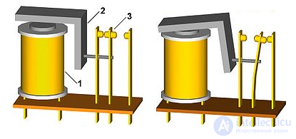
The operation of electromagnetic relays is based on the use of electromagnetic forces arising in a metal core when current passes through its coils. Relay parts are mounted on the base and closed with a lid. Above the core of the electromagnet is mounted a movable anchor (plate) with one or more contacts. Opposite them are the corresponding paired fixed contacts.
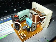
In the initial position, the anchor is held by a spring. When a control signal is applied, the electromagnet attracts the armature, overcoming its force, and closes or opens the contacts, depending on the design of the relay. After disabling the control voltage spring returns the anchor to its original position. In some models, electronic components can be embedded. This is a resistor connected to the coil winding for more accurate relay operation, or (and) a capacitor parallel to the contacts to reduce sparking and interference.
The controlled circuit is in no way electrically connected to the control circuit (this situation is often referred to in electrical engineering as dry contact). Moreover, in a controlled circuit, the magnitude of the current can be much greater than in the control circuit. The source of the control signal can be: low-current electrical circuits (for example, remote control), various sensors (light, pressure, temperature, etc.), and other devices that have minimum current and voltage at the output. Thus, the relays essentially perform the role of a discrete current, voltage, and power amplifier in an electrical circuit. This property of the relay, by the way, was widely used in the very first discrete (digital) computers. Subsequently, relays in digital computing were replaced first by lamps, then by transistors and microcircuits - operating in a key (switching) mode. Currently, there are attempts to revive the relay computers using nanotechnology.
Nowadays, in electronics and electrical engineering, relays are mainly used to control large currents. In circuits with low currents, transistors or thyristors are most often used for control.
When working with ultra-large currents (tens to hundreds of amps; for example, when cleaning metal by electrolysis) to eliminate the possibility of breakdown, the contacts of the controlled circuit are executed with a large contact area and immersed in oil (the so-called “oil cell”).
Relays are still very widely used in consumer electronics, especially for automatic switching on and off of electric motors (start-up relays), as well as in electric circuits of cars. For example, the start-up relay is necessarily present in the domestic refrigerator, as well as in washing machines. In these devices, the relay is much more reliable than electronics, since it is resistant to a current surge when the motor starts up and, especially, to a strong voltage surge when it is turned off.

Comments
To leave a comment
Electronics, Microelectronics, Element Base
Terms: Electronics, Microelectronics, Element Base