Lecture
1.1. Types and types of schemes
1.2. General requirements for the implementation of electrical circuits
1.3. Rules for the implementation of electrical concepts
Questions for self-test
Product diagrams of all industries are carried out manually or in an automated way, as well as electrical circuits of power facilities (power plants, electrical equipment of industrial enterprises, etc.) should be performed in accordance with GOST 2.701-84. This standard establishes the types and types of schemes and general requirements for their implementation, as well as the terms and definitions used in the design documentation.
Element - an integral part of a product that performs a specific function that cannot be further divided and obtain an alphanumeric designation (resistor, microcircuit, transformer, hydraulic drive).
Device - a set of elements that make up a single structure (block, module, kit or mechanism, etc.).
Functional group - a set of elements that perform their function in the product, but not separated into a separate structure (stabilizer, generator, etc.).
A functional part is an element, device or functional part that performs a specific functional purpose.
The functional chain is a line, a channel, a path of a specific purpose (image channel, synchronization node, etc.).
The interconnection line is the communication line in the diagram connecting the functional parts of the product.
An electrical link is a circuit line indicating the passage of a particular signal.
Depending on the displayed physical processes of a set of elements and relationships that make up the product (installation), the schemes are divided into types (Table 1.1).
Depending on the main purpose, the schemes are divided into types (Table 1.2). Accordingly, each scheme has its own alphanumeric code. For example, the electrical circuit has an EZ code.
Schemes (or instead of them) are issued as independent documents in a table containing information on the location of devices, connections, connection points and other information. Such documents are assigned a code consisting of the letter T and the code of the corresponding scheme. For example, the code of the table of compounds will be denoted by ТЭ4.
Table 1.1 Types of schemes
| Table 1.2 Types of schemes
|
In the title block of the document indicate the name of the product, as well as the name of the document "Table of connections".
Each scheme is assigned a designation according to GOST 2.201-80 as an independent design document.
A structural diagram is a document that defines the main functional parts of the product and the connections between them.
Functional diagram - a document explaining the processes occurring in the product or in its individual parts.
A schematic diagram is a document that defines a complete set of product elements and the connections between them with an explanation of the principle of operation.
Connection diagram - a document explaining the connections of the component parts of the product.
The wiring diagram is a document that defines the external connections of the product.
The general scheme is a document that defines the components of the complex and their connection with each other at the place of installation and operation.
Location map - a document defining the location of component parts at the installation site.
Combined (combined) scheme - a document that combines several types or types of schemes.
A scheme is a document on which the components of a product and the connections between them are shown with the help of certain UGOs.
Scheme sheet formats are selected in accordance with the requirements established in GOST 2.301-68 * and GOST 2.004-79.
Schemes performed without respecting the scale.
The graphic symbols of the functional parts and the communication lines connecting them should be placed on the diagram in such a way as to provide the best idea of the structure of the product and the interaction of its component parts.
The distance (clearance) between two adjacent lines of the graphic symbol should be at least 1.0 mm.
The distance between adjacent parallel lines of communication must be at least 3.0 mm.
The distance between the individual UGO must be at least 2.0 mm.
HUO elements are depicted in sizes established in the standards for conventional graphic symbols.
The dimensions of the CRB, as well as the thickness of their lines should be the same on all schemes for this product.
Graphic symbols on the diagrams should be made with lines of the same thickness as the communication lines.
HLI elements are depicted on the diagram in the position in which they are given in the relevant standards, or rotated by an angle of 90 ° . It is allowed to rotate the UGO at an angle of a multiple of 45 ° and to mirror it rotated.
Communication lines are made with a thickness of 0.2 mm to 1.0 mm, depending on the format of the scheme and the size of graphic images. The recommended thickness of communication lines is from 0.3 to 0.4 mm. Communication lines should consist of horizontal and vertical segments and have the least amount of kinks and mutual intersections. Communication lines are allowed to break off. The clippings end with arrows. Around the arrows indicate the designation places (connection, polarity, etc.).
The list of circuit elements of the electric principal, which is drawn up in the form of a table, filled from top to bottom (Fig. 1.1), is placed on the first sheet of the circuit or carried out in the form of an independent document.
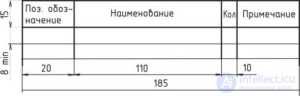
Fig. 1.1. Sizes of the list of items
In the columns of the list indicate the following data:
When executing the list of elements on the first sheet of the scheme, it is placed above the title block. The distance between the list of elements and the main title must be at least 12 mm. The continuation of the list of elements is placed to the left of the title block, repeating the heading of the table. In the form of an independent document, the list of elements is carried out on A4 format. The main inscription and additional columns to it are performed according to GOST 2.104-68 * (form 2 and 2a). A code is assigned to the document, for example, for the list of elements of the electrical circuit diagram - PE3.
When the scheme field is broken down into zones, the list of elements is supplemented with the “Zone” column, indicating in it the zone designation or the alphanumeric designation of the row and column of the scheme field (Fig. 1.2).
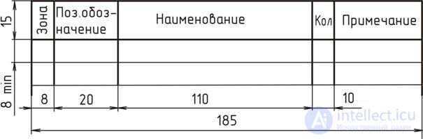
Fig. 1.2. The form of the list of elements when using zones in the field of the scheme
The elements of the list are written in groups in alphabetical order letter numbers (the alphabet is Latin). Within each group that has the same literal positional values, the elements have ascending sequence numbers.
Records of elements included in each device (functional group) begin with the name of the device (or functional group), which is recorded in the “Name” column and underlined. With automated documentation, the device name (functional group) is allowed not to be underlined.
Below the name of the device should be left one free line, above - at least one free line.
It is allowed to place on the schemes various technical data, the nature of which is determined by the purpose of the scheme. Such information is indicated either near the graphic symbols (if possible, to the right or above), or in the free field of the drawing.
Textual data are given on the diagram and in those cases when the information contained in them is impractical or impossible to express graphically or symbols.
Inscriptions, signs or graphics intended for drawing on a product, on the scheme enclosed in quotes.
In the inscriptions on the diagrams should not be used abbreviations of words, with the exception of generally accepted or established standards.
Circuit diagram is the most complete electrical circuit of the product. According to GOST 2.702-75 *, all electrical elements or devices necessary for the implementation and control in a product of specified electrical processes, all electrical connections between them, as well as electrical elements (connectors, clamps, etc.) that end input and output circuits.
Schemes are performed for products that are in the off position.
Elements and devices are depicted on the schemes in a combined or spaced manner. In a combined way, the constituent parts of the elements or devices are depicted in the diagram in close proximity to each other. In an exploded manner, the constituent parts of elements or devices are depicted in a diagram in different places so that the individual chains of the product are most visible. When performing schemes it is recommended to use the combined method.
When depicting different functional chains on one circuit, it is allowed to distinguish them by the thickness of the lines. On one scheme it is recommended to use no more than 3 sizes of lines in thickness. If necessary, the corresponding explanations are placed on the scheme field.
To simplify the scheme, several electrically uncoupled communication lines are allowed to merge into the group communication line, but when approaching the contacts (elements) each communication line is depicted as a separate line. When merging communication lines, each communication line is marked at the merging point and, if necessary, at both ends, with symbols. Designation of lines is affixed in accordance with the requirements given in GOST 2.751-73.
Sequence numbers of reference signs should be assigned in accordance with the sequence of arrangement of elements (devices) in the scheme from top to bottom in the direction from left to right.
Positional notation is put on the diagram next to the UGO elements (devices) on the right side or above them.
It is recommended to indicate the characteristics of the input and output circuits in the diagram.
1. What is called a circuit?
2. How does the type of scheme differ from the type of scheme?
3. What is the circuit element called?
4. What is shown on the layout?
5. What is the difference between the block diagram and the functional diagram?
6. What is the difference between the concepts of the functional part and the functional group?
7. What is the recommended thickness of HWP lines?

Comments
To leave a comment
Electronics, Microelectronics, Element Base
Terms: Electronics, Microelectronics, Element Base