Lecture
This term has other meanings, see Capacitor (s).
See also: varicap
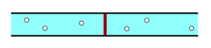
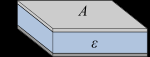
The basis of the design of the capacitor - two conductive plates, between which there is a dielectric
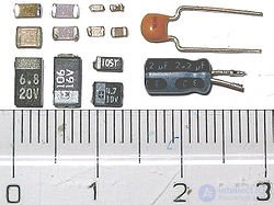
On the left - surface mounted capacitors; right - capacitors for surround installation; on top - ceramic; bottom - electrolytic. On tantalum capacitors (on the left), a “+” is marked with a strip, on the aluminum (on the right) they are marked “-”.

SMD capacitor on the board, macro
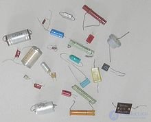
Various capacitors for surround installation
Condenser (from the Latin. Condensare - “condense”, “thicken”) - a two-port network with a certain or variable value of capacity and low conductivity; device for the accumulation of charge and energy of the electric field.
The capacitor is a passive electronic component. In the simplest version, the design consists of two electrodes in the form of plates (called plates ), separated by a dielectric, the thickness of which is small compared to the dimensions of the plates (see fig.). Practically used capacitors have many layers of dielectric and multilayer electrodes, or strips of alternating dielectric and electrodes rolled into a cylinder or parallelepiped with rounded four edges (due to winding).
In 1745, the German canon Ewald Jürgen von Kleist and, independently of him, the Dutch physicist Peter van Muschenbruck, acquired the design-prototype of an electric condenser, the Leyden jar, in Leiden [1] . The first capacitors, consisting of two conductors separated by a non-conductor (dielectric), usually referred to as an Epinus capacitor or electrical sheet, were created earlier [2] .
A capacitor in a DC circuit can conduct current at the moment of its inclusion in the circuit (charge or recharge of the capacitor occurs), after the end of the transient process the current through the capacitor does not flow, since its plates are separated by a dielectric. In the circuit of the alternating current, he conducts a collar of the alternating current by cyclically recharging the capacitor, closed by the so-called bias current.
In the hydraulic analog method, a capacitor is a flexible membrane inserted into a pipe. The animation shows a membrane that stretches and contracts under the action of water flow, which is similar to the charge and discharge of a capacitor under the action of an electric current.
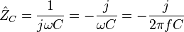
From the point of view of the complex amplitude method, a capacitor has a complex impedance
 ,
,
, where j is the imaginary unit, ω is the cyclic frequency ( rad / s ) of the flowing sinusoidal current, f is the frequency in Hz , C is the capacitance of the capacitor ( farad ). It also follows that the capacitor reactance is equal to:  . For DC, the frequency is zero, therefore, the capacitor reactance is infinite (in the ideal case).
As the frequency changes, the dielectric constant of the dielectric and the degree of influence of the parasitic parameters — its own inductance and loss resistance — change. At high frequencies, any capacitor can be considered as a series of ruts *** body circuit formed by capacitance C , self-inductance L C and loss resistance R n .
The resonant frequency of the capacitor is equal to
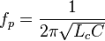
When f> f p, the capacitor in the AC circuit behaves like an inductor. Consequently, it is advisable to use a capacitor only at frequencies f p , at which its resistance is capacitive in nature. Usually the maximum operating frequency of a capacitor is about 2-3 times lower than the resonant one.
Capacitor can store electrical energy. Charged capacitor energy:
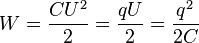
where U is the voltage (potential difference) to which the capacitor is charged, and q is the electric charge.
In Russia, conventional graphic symbols of capacitors on the circuits must comply with GOST 2.728-74 [3] or the international standard IEEE 315—1975:
| Designation in accordance with GOST 2.728-74 |
Description |
|---|---|
 |
Fixed capacitor |
 |
Polarized (polar) capacitor |
 |
Variable Capacity Trimmer Capacitor |
 |
Varicap |
On electrical schematics, the nominal capacitance of capacitors is usually indicated in microfarads (1 μF = 1 · 10 6 pF = 1 · 10 −6 F) and picofarad, but often in nanofarads (1 nF = 1 · 10 −9 F). With a capacity of not more than 0.01 μF, the capacitance of the capacitor is indicated in picofarad, while it is permissible not to indicate the unit of measurement, that is, the postfix “pF” is omitted. When designating the nominal capacity in other units indicate the unit of measurement. For electrolytic capacitors, as well as for high-voltage capacitors on the circuits, after designation of capacitance, indicate their maximum operating voltage in volts (V) or kilovolts (kV). For example: “10 uF x 10 V”. For variable capacitors indicate the range of changes in capacity, for example: "10 - 180". Currently, capacitors with nominal capacitances are made from decimal-logarithmic series of values Е3, Е6, Е12, Е24, that is, for one decade there are 3, 6, 12, 24 values, so that the values with the corresponding tolerance (spread) overlap the whole decade.
Capacity
The main characteristic of a capacitor is its capacity , which characterizes the ability of a capacitor to accumulate electric charge. In the designation of the capacitor appears the value of the nominal capacity, while the actual capacity can vary significantly depending on many factors. The actual capacitance of a capacitor determines its electrical properties. So, by definition of capacity, the charge on the plate is proportional to the voltage between the plates ( q = CU ). Typical capacitor capacitance values range from picofarads to thousands of microfarads. However, there are capacitors (ionistors) with a capacity of up to tens of farads.
The capacity of a flat capacitor, consisting of two parallel metal plates of area S each, is located at a distance d from each other, in the system is expressed by the formula:  where
where  - the dielectric constant of the medium, filling the space between the plates (in vacuum is equal to one),
  —Electric constant numerically equal to 8.854187817 · 10 −12 F / m. This formula is valid only when d is much smaller than the linear dimensions of the plates.
For larger capacities, capacitors are connected in parallel. In this case, the voltage between the plates of all capacitors is the same. The total capacity of a battery of parallel connected capacitors is equal to the sum of the capacities of all capacitors included in the battery.
 or
or 
If the distance between the plates and the properties of the dielectric are the same for all parallel-connected capacitors, then these capacitors can be represented as one large capacitor, divided into fragments of a smaller area.
When the capacitors are connected in series, the charges of all the capacitors are the same, since they come from the power source only to the external electrodes, and on the internal electrodes they are obtained only by separating the charges that previously neutralized each other. The total capacity of a battery of series- connected capacitors is equal to
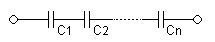
 or
or 
This capacity is always less than the minimum capacity of the capacitor entering the battery. However, with a series connection, the possibility of breakdown of capacitors decreases, since each capacitor accounts for only a fraction of the potential difference of the voltage source.
If the area of the plates of all capacitors connected in series is the same, then these capacitors can be represented as one large capacitor, between the plates of which is a stack of dielectric plates of all its component capacitors.
Specific capacity
Capacitors are also characterized by specific capacitance - the ratio of capacitance to volume (or mass) of the dielectric. The maximum value of the specific capacitance is achieved with a minimum thickness of the dielectric, but at the same time its breakdown voltage decreases.
Energy density
The energy density of an electrolytic capacitor depends on the design. The maximum density is achieved for large capacitors, where the body weight is small compared to the mass of the plates and the electrolyte. For example, with an EPCOS B4345 capacitor with a capacity of 12,000 microfarads, a maximum allowable voltage of 450 V and a mass of 1.9 kg, the energy density at maximum voltage is 639 J / kg or 845 J / l. This parameter is especially important when using a capacitor as an energy storage device, followed by its instantaneous release, for example, in a Gauss gun.
Rated voltage
Another, no less important characteristic of capacitors is the rated voltage - the voltage value indicated on the capacitor, at which it can operate under given conditions during its service life while maintaining the parameters within acceptable limits.
The nominal voltage depends on the design of the capacitor and the properties of the materials used. During operation, the voltage on the capacitor should not exceed the nominal. For many types of capacitors, with an increase in temperature, the allowable voltage decreases, which is associated with an increase in the thermal velocity of the charge carriers and, accordingly, a decrease in the requirements for the formation of electrical breakdown.
Polarity
Modern condensers, destroyed without an explosion due to the special exploding design of the top cover. Destruction is possible due to a violation of the mode of operation (temperature, voltage, polarity) or aging. Capacitors with a broken lid are practically inoperative and require replacement, and if it is just swollen but not yet broken, then it is likely that it will soon fail or the parameters will change dramatically, which will make its use impossible.
Many capacitors with an oxide dielectric (electrolytic) function only with the correct polarity of the voltage due to the chemical features of the interaction of the electrolyte with the dielectric. When the voltage is reversed, electrolytic capacitors usually fail due to chemical destruction of the dielectric, followed by an increase in current, boiling up of the electrolyte inside and, as a result, with the likelihood of a body exploding.
Danger of destruction (explosion)
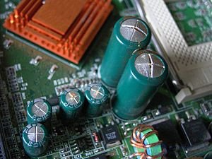
Electrolytic capacitor blasts are a fairly common occurrence. The main cause of explosions is condenser overheating, caused in most cases by leakage or increase of equivalent series resistance due to aging (relevant for impulse devices). In modern computers, overheating of condensers is also a very common cause of their failure when they are near sources of increased heat generation (cooling radiators).
To reduce damage to other parts and injuries of personnel in modern large-capacity capacitors, an ejection safety valve is installed or the housing is notched (often it can be seen as a cross or in the form of X, K or T letters on the butt end of a cylindrical body, covered with plastic). With an increase in the internal pressure, the valve plug is knocked out or the casing collapses along the notch, the electrolyte vapor escapes in the form of caustic gas and even liquid splashes. In this case, the destruction of the capacitor case occurs without explosion, scattering of the plates and the separator.
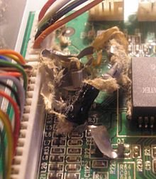
An exploded electrolytic capacitor on a printed circuit board liquid crystal monitor. The paper separator fibers of the plates and the unfolded aluminum foil plates are visible.
Old electrolytic capacitors were produced in sealed enclosures and the design of their enclosures did not provide for explosion safety. The speed of fragments in the explosion of the body of obsolete capacitors can be large enough to injure a person.
Unlike electrolytic, the explosiveness of semiconductor (tantalum) capacitors is related to the fact that such a capacitor is actually an explosive mixture: tantalum serves as a fuel, and manganese dioxide as an oxidizer, and both of these components are mixed in the form of a fine powder . During the breakdown of a capacitor or in case of its accidental reversal, the heat released during the flow of current initiates a reaction between these components, occurring in the form of a strong flash with a pop, which is accompanied by the scattering of sparks and shell fragments. The strength of such an explosion is quite large, especially for large capacitors, and can damage not only the neighboring radio elements, but also the board. With a close arrangement of several capacitors it is possible to burn through the housings of adjacent capacitors, which leads to a simultaneous explosion of the whole group.
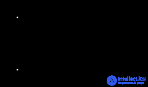
Real capacitors, in addition to capacity, also have their own series and parallel resistance and inductance. With sufficient accuracy for practice, the equivalent circuit of a real capacitor can be represented as shown in the figure, where all two-poles are assumed to be ideal.
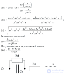
Equivalent scheme of a real capacitor and some formulas.
C 0 is the capacitor's own capacity;
R d - insulation resistance of the capacitor;
R s - equivalent series resistance;
L i - equivalent series inductance.
The electrical resistance of the capacitor dielectric insulation, surface leakage R d and self-discharge
Insulation resistance is the resistance of a capacitor to a direct current, defined by the relation R d = U / I ut , where U is the voltage applied to the capacitor, I ut is the leakage current.
Due to the leakage current flowing through the dielectric layer between the plates and on the surface of the dielectric, the pre-charged capacitor loses charge over time (self-discharge of the capacitor). Often, in the specifications for capacitors, the leakage resistance is determined through the time constant T of the self-discharge of the capacitor, which is numerically equal to the product of the capacitance and the leakage resistance:

T is the time during which the initial voltage on a capacitor not connected to an external circuit decreases by a factor of e .
Good capacitors with polymer and ceramic dielectrics have constant self-discharge times of many hundreds of thousands of hours.
Equivalent series resistance - R s
Эквивалентное последовательное сопротивление (ЭПС (англ. ESR ), внутреннее сопротивление) обусловлено, главным образом, электрическим сопротивлением материала обкладок и выводов конденсатора и контакта(-ов) между ними, а также учитывает потери в диэлектрике. Обычно ЭПС возрастает с увеличением частоты тока, протекающего через конденсатор, вследствиеповерхностного эффекта.
В большинстве практических случаев этим параметром можно пренебречь, но, иногда (напр., в случае использованияэлектролитических конденсаторов в фильтрах импульсных блоков питания), достаточно малое его значение существенно для надёжности и устойчивости работы устройства. В электролитических конденсаторах, где один из электродов являетсяэлектролитом, этот параметр при эксплуатации со временем деградирует, вследствие испарения растворителя из жидкого электролита и изменения его химического состава, вызванного взаимодействием с металлическими обкладками, что происходит относительно быстро в низкокачественных изделиях (см. Capacitor plague (англ.)).
Некоторые схемы (например, стабилизаторы напряжения) критичны к диапазону изменения ЭПС конденсаторов в своих цепях. Это связано с тем, что при проектировании таких устройств инженеры учитывают этот параметр в фазочастотной характеристике (ФЧХ) обратной связи стабилизатора. Существенное изменение со временем ЭПС применённых конденсаторов изменяет ФЧХ, что может привести к снижению запаса устойчивости контуров авторегулирования, и, даже, к самовозбуждению.
Существуют специальные приборы (ESR-метр ( англ. )) для измерения этого достаточно важного параметра конденсатора, по которому можно часто определить пригодность его дальнейшего использования в определённых целях. Этот параметр, кроме собственно ёмкости (ёмкость — это основной параметр) — часто имеет решающее значение в исследовании состояния старого конденсатора и принятия решения, стоит ли использовать его в определённой схеме, или он прогнозируемо выйдет за пределы допустимых отклонений.
Эквивалентная последовательная индуктивность — L i
Equivalent series inductance is mainly due to the inherent inductance of the capacitor plates and terminals. The result of this distributed parasitic inductance is the conversion of a capacitor in a coil circuit with a characteristic natural resonance frequency . This frequency can be measured and is usually indicated in the parameters of the capacitor either explicitly or as the recommended maximum operating frequency.
Dielectric loss tangent
The dielectric loss tangent is the ratio of the imaginary and real parts of the complex dielectric constant. 
Потери энергии в конденсаторе определяются потерями в диэлектрике и обкладках. При протекании переменного тока через конденсатор векторы напряжения и тока сдвинуты на угол  где δ — угол диэлектрических потерь. При отсутствии потерь δ = 0. Тангенс угла потерь определяется отношением активной мощности P а креактивной P р при синусоидальном напряжении определённой частоты. Величина, обратная tg δ, называется добротностью конденсатора. Термины добротности и тангенса угла потерь применяются также для катушек индуктивности и трансформаторов.
Температурный коэффициент ёмкости ( ТКЕ )
ТКЕ — относительное изменение ёмкости при изменении температуры окружающей среды на один градус Цельсия (кельвин). ТКЕ определяется так:
 .
.
Where  — изменение ёмкости, вызванное изменением температуры на
  .
.
Таким образом, изменение ёмкости от температуры (при не слишком больших изменениях температуры) выражается линейной функцией:
 ,
,
Where — изменение температуры в °C или К относительно нормальных условий, при которых специфицировано значение ёмкости,  — ёмкость при нормальных условиях. TKE применяется для характеристики конденсаторов с практически линейной зависимостью ёмкости от температуры. Однако ТКЕ указывается в спецификациях не для всех типов конденсаторов.
Для конденсаторов, имеющих существенно нелинейную зависимость ёмкости от температуры и для конденсаторов с большими изменениями ёмкости от воздействия температуры окружающей среды в спецификациях нормируются относительное изменение ёмкости в рабочем диапазоне температур или в виде графика зависимости ёмкости от температуры.
Диэлектрическая абсорбция
Если заряженный конденсатор быстро разрядить до нулевого напряжения путём подключения низкоомной нагрузки, а затем снять нагрузку и наблюдать за напряжением на выводах конденсатора, то мы увидим, что напряжение на обкладках снова появится как если бы мы разрядили конденсатор не до нуля. Это явление получило название диэлектрическая абсорбция (диэлектрическое поглощение). Конденсатор ведёт себя так, словно параллельно ему подключено множество последовательных RC -цепочек с различной постоянной времени. Интенсивность проявления этого эффекта зависит в основном от свойств диэлектрика конденсатора.
Подобный эффект можно наблюдать практически на всех типах диэлектриков. В электролитических конденсаторах он особенно ярок и является следствием химических реакций между электролитом и обкладками. У конденсаторов с твердым диэлектриком (например, керамических и слюдяных) эффект связан с остаточной поляризацией диэлектрика. Наименьшим диэлектрическим поглощением обладают конденсаторы с неполярными диэлектриками: тефлон (фторопласт), полистирол, полипропилени т. п.
Эффект зависит от времени зарядки конденсатора, времени закорочения, иногда от температуры. Количественное значение абсорбции принято характеризовать коэффициентом абсорбции , который определяется в стандартных условиях.
Особое внимание в связи с эффектом следует уделять измерительным цепям постоянного тока: прецизионным интегрирующим усилителям, устройствам выборки-хранения, некоторым схемам на переключаемых конденсаторах.
Паразитный пьезоэффект
Многие керамические материалы, используемые в качестве диэлектрика в конденсаторах (например, титанат бария, обладающий очень высокой диэлектрической проницаемостью в не слишком сильных электрических полях) проявляют пьезоэффект — способность генерировать напряжение на обкладках при механических деформациях. Это характерно для конденсаторов с пьезоэлектрическими диэлектриками. Пьезоэффект ведёт к возникновению электрических помех, в устройствах, где использованы такие конденсаторы при воздействии акустического шума или вибрации на конденсатор. Это нежелательное явление иногда называют («микрофонным эффектом»).
Также, подобные диэлектрики проявляют и обратный пьезоэффект — при работе в цепи переменного напряжения происходит знакопеременная деформация диэлектрика, генерирующая акустические коле***ния, порождающие дополнительные электрические потери в конденсаторе.
Самовосстановление
Конденсаторы с металлизированным электродом (бумажный и пленочный диэлектрик) обладают важным свойством самовосстановления (англ. self-healing, cleaning) электрической прочности после пробоя диэлектрика. Механизм самовосстановления заключается в отгорании металлизации электрода после локального пробоя диэлектрика посредством микродугового электрического разряда.
Слюдяной герметичный конденсатор в металлостеклянном корпусе типа «СГМ» для навесного монтажа
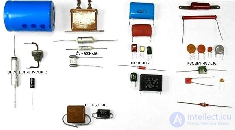
Основная классификация конденсаторов проводится по типу диэлектрика в конденсаторе. Тип диэлектрика определяет основные электрические параметры конденсаторов: сопротивление изоляции, стабильность ёмкости, величину потерь и др.
По виду диэлектрика различают:
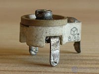
Ceramic Trimmer Capacitor
In addition, capacitors differ in the possibility of changing their capacity:
Depending on the purpose, it is possible to conditionally divide capacitors into general-purpose and special-purpose capacitors. General purpose capacitors are used in almost all types and classes of equipment. Traditionally, they include the most common low-voltage capacitors, which are not subject to special requirements. All other capacitors are special. These include high-voltage, pulse, interference suppression, dosimetric, starting and other capacitors.
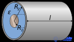
Also distinguish capacitors in the form of plates: flat, cylindrical, spherical and others.
| Title | Capacity | Electric field | Scheme |
|---|---|---|---|
| Flat capacitor | 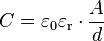 |
 |
 |
| Cylindrical capacitor | 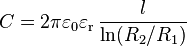 |
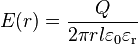 |
 |
| Spherical capacitor | 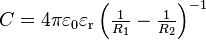 |
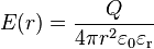 |
 |
| Sphere |  |
| Condenser type | Used dielectric | Features / Applications | disadvantages |
|---|---|---|---|
|
Capacitors with solid organic dielectric |
|||
| paper capacitors | |||
| AC oil capacitors | Oiled paper | Mainly developed to provide very large capacitances for industrial use in AC circuits, while maintaining high currents and high peak voltages with the frequency of the power supply network. Their tasks include starting and running AC electric motors, phase separation, power factor correction, voltage stabilization, working with control equipment, etc. | Limited by low operating frequency, since high frequencies have high dielectric losses. |
| DC oil capacitors | Paper or its combination with PET | Designed to operate at a constant current for filtering, doubling the voltage, preventing the formation of an arc, as pass-through and separation capacitors | In the presence of pulsations, a reduction in the operating voltage is required according to the graphs provided by the manufacturer. They are larger in comparison with analogs with polymer dielectrics. |
| Paper capacitors | Paper / impregnated paper | Impregnated paper was widely used in old capacitors. The impregnation was wax, oil, or epoxy. Some of these capacitors are still used for high voltage operation, but in most cases, film capacitors are now used instead. | Big size. Mostly hygroscopic, due to which they absorb moisture from the air even in the presence of a plastic body and impregnation. Absorbed moisture impairs their characteristics, increasing dielectric loss and lowering the insulation resistance. |
| Metallized Paper Capacitors | Paper | Smaller size than paper foil capacitors | Suitable only for low current applications. Instead, metallized film capacitors have become widely used. |
| Energy storage capacitors | Condenser kraft paper impregnated with castor oil or similar liquid with a high dielectric constant, and foil plates | Designed to operate in a pulsed mode with a high discharge current. Better tolerate a change in voltage polarity than many polymer dielectrics. Usually used in pulsed lasers, Marx generators, for pulsed welding, with electromagnetic molding and other tasks that require the use of high-power pulses. | Have a large size and weight. Their power consumption is much less than that of capacitors using polymer dielectrics. . Not capable of self-healing. Failure of such a capacitor can be catastrophic due to the large amount of stored energy. |
| film capacitors | |||
| Polyethylene terephthalate condensers | Polyethylene terephthalate film | Less than paper or polypropylene capacitors with similar characteristics. Can use strips of foil, metallized film, or combinations thereof. PET capacitors are almost completely replaced by paper for tasks where work with direct (constant) current is required. They have operating voltages of up to 60,000 volts at a constant current and operating temperatures of up to 125 ° C. Possess low hygroscopicity. | Temperature stability is lower than that of paper. Can be used with low-frequency alternating current, but unsuitable at high-frequency due to excessive heating of the dielectric. |
| Polyamide capacitors | Polyamide | Operating temperature up to 200 ° C. High insulation resistance, good stability, low loss tangent. | Big sizes and high price. |
| Kapton capacitors | Polyimide film brand Kapton | Similar to PET, but have a significantly higher operating temperature (up to 250 ° C). | More expensive than PET. Temperature stability is lower than that of paper capacitors. They can also be used only at low-frequency alternating current, since at high frequencies the dielectric is strongly heated. |
| Polycarbonate capacitors | Polycarbonate | They have better insulation resistance, loss tangent and dielectric adsorption compared to polystyrene capacitors. Possess the best moisture resistance. Temperature coefficient about ± 80 ppm. Withstand full operating voltage over the entire temperature range (from −55 ° C to 125 ° C) | Maximum operating temperature is limited to 125 ° C. |
| Polysulfone capacitors | Polysulfone | Similar to polycarbonate. Can withstand full rated voltage at relatively high temperatures. Moisture absorption of about 0.2%, which limits their stability. | Low availability and high cost. |
| Polypropylene capacitors | Polypropylene | Extremely low loss tangent, higher dielectric strength than polycarbonate and PET capacitors. Low hygroscopicity and high insulation resistance. Can use strips of foil, metallized film, or combinations thereof. The film is compatible with self-healing technology, which increases reliability. Can operate at high frequencies, including at high power, for example, for induction heating (often with water cooling), due to very low dielectric losses. At higher capacitances and operating voltages, for example, from 1 to 100 microfarads and voltages up to 440 volts AC, can be used as starters for working with certain types of single-phase electric motors. | More susceptible to damage from short-term overvoltages or polarity reversal than oil-impregnated paper capacitors. |
| Polystyrene capacitors | Polystyrene | Excellent film high-frequency capacitors for general use. They have excellent stability, high moisture resistance and low negative temperature coefficient, which allows them to be used to compensate for the positive temperature coefficient of other components. Ideal for low-power high-frequency and precision analog applications. | Maximum operating temperature is limited to +85 ° C. Relatively large in size. |
| Fluoroplastic capacitors | Polytetrafluoroethylene | Excellent film high-frequency capacitors for general use. Very low dielectric loss. Operating temperature up to 250 ° C, high insulation resistance, good stability. Used in critical tasks. | Large size due to low dielectric constant, higher price in comparison with other capacitors. |
| Metallized polyethylene terephthalate and polycarbonate capacitors | PET or Polycarbonate | Reliable and significantly smaller. Fine plating can be used to give them self-healing properties. | Fine plating limits maximum current. |
|
Capacitors with solid inorganic dielectric |
|||
| Multi-Level Plate Mica Capacitors | Mica | The advantages of these capacitors are based on the fact that their dielectric is inert. It does not change with time either physically or chemically, and also has good temperature stability. Possess very high resistance to corona discharge. | Without proper sealing, they are subject to moisture, which degrades their parameters. High price due to the rarity and high quality dielectric, as well as manual assembly. |
| Metallized or silver mica capacitors | Mica | The same advantages, in addition, are more resistant to moisture. | Higher price. |
| Glass capacitors | Glass | Similar to mica. Stability and frequency response is better than mica. Very reliable, very stable, resistant to radiation. | High price. |
| Temperature compensated ceramic capacitors | A mixture of complex compounds of titanates | Cheap, tiny, possess excellent high-frequency characteristics and good reliability. Predictable linear change in capacity relative to temperature. There are products that can withstand up to 15,000 volts | A change in capacity at a different applied voltage, frequency, is subject to aging. |
| Ceramic capacitors with high dielectric constant | Dielectric based on barium titanate | Smaller than temperature-compensated capacitors due to the higher dielectric constant. Available for voltages up to 50,000 volts. | They have lower temperature stability, the capacitance varies significantly with different applied voltages. |
|
Capacitors with oxide dielectric |
|||
| Aluminum Electrolytic Capacitors | Aluminium oxide | The huge ratio of capacity to volume, inexpensive, polar. Mainly used as smoothing and supply capacitors in power supplies. The time between failures of the condenser with the maximum allowable operating temperature of 105 ° C when calculating is up to 50,000 hours at a temperature of 75 ° C | High leakage currents, high internal resistance and inductance limit their use at high frequencies. They have low temperature stability and poor parameter deviations. They may explode if the permissible parameters are exceeded and / or overheated, when reverse voltage is applied. The maximum voltage is about 500 volts. |
| Tantalum capacitors | Tantalum oxide | Large capacity to volume ratio, small size, good stability, large operating temperature range. Widely used in miniature equipment and computers. Available in both polar and non-polar versions. Solid tantalum capacitors have much better performance than liquid electrolyte. | More expensive aluminum electrolytic capacitors. The maximum voltage is limited to a bar of about 50 volts. Explode when exceeding the permissible current, voltage or rate of rise of voltage, as well as when applying a voltage of incorrect polarity. |
| Solid capacitors | Aluminum oxide, oxidantalum | Instead of the traditional liquid electrolyte, a special conductive organic polymer or polymerized organic semiconductor is used. Time between failures ~ 50,000 hours at a temperature of 85 ° C. EPS is less than liquid electrolytic and weakly dependent on temperature. Do not explode. | More expensive than usual. At 105 ° C, the service life is as in ordinary electrolytic. Operating voltages up to 35 V. |
|
Electric double layer capacitors |
|||
| Electric Double Layer Capacitors (Ionistors) | Thin electrolyte layer activated carbon | Huge capacity relative to volume, small size, low equivalent series resistance. Numbers in the hundreds and even thousands of farads are available. This is a relatively new technology. Usually used to temporarily power equipment when replacing batteries. They can be charged and discharged with more currents than batteries, which makes them valuable for hybrid cars. Polar, have a low rated voltage (volts per capacitor cell). Groups of cells are connected in series to increase the total operating voltage. | Relatively high cost. |
| Lithium ion capacitors | Lithium ion | Lithium-ion capacitors have greater energy capacity comparable to batteries, safer in comparison with lithium-ion batteries, in which a vigorous chemical reaction starts at high temperatures. Compared with ionistors, they have a higher output voltage. Their specific power is comparable, but the energy density of Li-ion capacitors is much higher. | New technology. |
|
Vacuum Capacitors |
|||
| Vacuum condensers | Vacuum condensers use glass or ceramic flasks with concentric cylindrical electrodes. | Extremely small losses. Used for high-power, high-voltage radio-frequency tasks, such as induction heating, where even small losses lead to excessive heating of the capacitor itself. With limited current sparks can have a self-healing. | Very high price, fragility, large size, low capacity. |
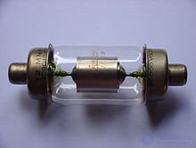
12 pF, 20 kV vacuum capacitor of constant capacity.
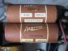
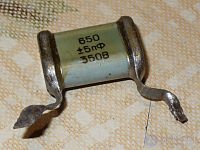
Two 8 uF, 525 V paper electrolytic capacitors in the radio of the 1930s. [6]
Capacitors are used in almost all areas of electrical engineering.
Существуют две системы обозначения советских/российских конденсаторов: буквенная (старая) и цифровая (новая).
Старая система обозначений
Буквенная система распространяется на конденсаторы, разработанные до 1960 года. В этой системе первая буква К означает конденсатор, вторая — тип диэлектрика (Б — бумажный, С — слюдяной, К — керамический, Э — электролитический и так далее...), третья — конструктивные особенности (герметичность исполнения или условия эксплуатации). Для упрощения системы обозначений часто первую букву К пропускают, оставляя вторую и последующие [7] .
Новая система обозначений
В соответствии с новой (цифровой) системой маркировки конденсаторы делятся на группы по виду диэлектрика, назначению и варианту исполнения [8] . Согласно этой системе, первая буква «К» означает «конденсатор», дальше следует цифра, обозначающая вид диэлектрика, и буква, указывающая, в каких цепях может использоваться конденсатор; после неё стоит номер разработки или буква, указывающая вариант конструкции [9] .
| Фото на Викискладе ? |

есть еще безиндукционнные конденсаторы
есть полилмерные
есть трехполярные
есть сдвоенные конденсаторы
Comments
To leave a comment
Electronics, Microelectronics, Element Base
Terms: Electronics, Microelectronics, Element Base