Lecture
Full-wave bridge rectifier
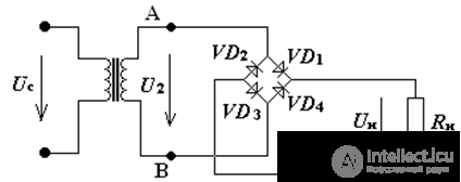
Fig.1 Full-wave bridge rectifier
The principle of operation of the bridge rectifier
The bridge circuit diodes connected to the secondary winding of the transformer Fig.1,
each pair of diodes works alternately VD1 VD3 and VD2VD4: on time diagrams in Fig.2
in the time interval 0-T / 2 open VD1VD3, closed VD2VD4 in the load current flows In;
in the time interval T / 2-T closed VD1VD3, open VD2VD4 in the load current flows In;
the frequency of the ripples of the rectified voltage is twice the network frequency
f p = 2fs = 100, Hz.
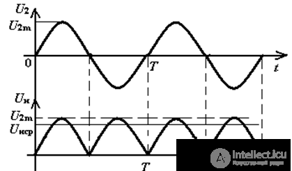
Fig.2. Timing Diagrams of Bridge Rectifier
The main parameters of the bridge rectifier
1. Mean Straighten Voltage:

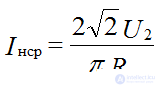
2. Mean rectified current:
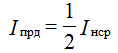
Direct current diode:
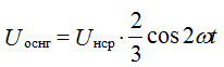
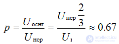
3. Expanding the voltage on the load in a Fourier series, we obtain the numerical value of the ripple coefficient for the bridge rectifying circuit:

The amplitude of the main second harmonic frequency 2ω:
Therefore, the ripple coefficient will be equal to:
The maximum reverse voltage on each of the closed diodes has such a value as in a half-wave rectifier, since they are connected in parallel with respect to the input:
U2m = √2U2;
Uobrmax = π • Unsr; Uomax = √2U2
The main disadvantage is a large number of diodes.
Currently, semiconductor rectifier blocks are produced according to bridge circuit (КЦ402, КЦ403, etc.

Comments
To leave a comment
Electronics, Microelectronics, Element Base
Terms: Electronics, Microelectronics, Element Base