Lecture
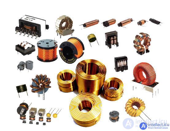
Inductor (inductance)- a helical, spiral or helical coil made of a rolled insulated conductor, which has significant inductance with a relatively small capacitance and low active resistance. As a result, when an alternating electric current flows through the coil, its significant inertia is observed.
They are used to suppress noise, smooth out ripples, store energy, limit alternating current in resonant (oscillatory circuit) and frequency-selective circuits, as inductors of artificial delay lines with lumped parameters, create magnetic fields, displacement sensors, and so on.
Inductance is a passive single-port element.


where is an arbitrary function of two variables.
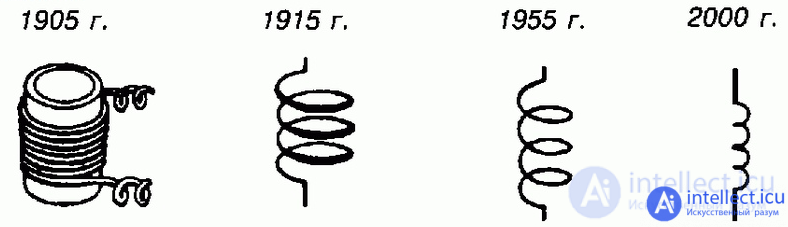
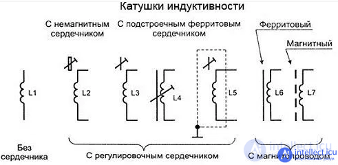
Designation on electrical concepts
When used to suppress noise, smooth out ripples of electric current, isolate (decouple) the high frequency of different parts of the circuit and store energy in the magnetic field of the core, it is often called a choke .
In power electrical engineering (to limit the current when, for example, a short circuit in the power line) is called a reactor .
A cylindrical inductor, the length of which is much greater than the diameter, is called a solenoid , the magnetic field inside the long solenoid is uniform. In addition, often called a solenoid device that performs mechanical work due to the magnetic field when drawing in a ferromagnetic core, or an electromagnet . In electromagnetic relays they call a relay winding , less often - an electromagnet.
The heating inductoris a special inductor, a working body of induction heating installations.
When used for energy storage, they are called induction storage .
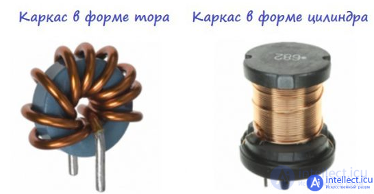
Structurally, it is made in the form of helical or helical (winding diameter varies along the length of the coil) coils of single-layer or multi-layer windings of an insulated single-core or multi-strand (littsendrat) conductor on a dielectric frame of round, rectangular or square cross section, often a noroidal frame or, when using thick wire and small number of turns - without frame. Sometimes, to reduce the distributed parasitic capacitance when used as a high-frequency inductor, single-layer inductors are wound with a "progressive" step - the winding step smoothly changes along the length of the coil. The winding can be either single-layer (ordinary and in increments), or multi-layer (ordinary, lined, such as "universal"). Winding "wagon" has a lower parasitic capacity. Often, again, to reduce stray capacitance,winding is performed sectionally, groups of turns are separated spatially (usually in length) from each other.
To increase inductance, coils are often provided with a closed or open ferromagnetic core. High frequency interference suppression chokes have ferrodielectric cores: ferrite, fluxtrol, carbonyl iron. Inductors designed to smooth out pulsations of industrial and sound frequencies have cores made of electrical steel or magnetically soft alloys (permalloys). Also, cores (usually ferromagnetic) are used to change the inductance of the coils to a small extent by changing the position of the core relative to the winding. At high frequencies, when ferrodielectrics lose high magnetic permeability and sharply increase losses, metal (brass) cores are used.
On printed circuit boards of electronic devices, flat inductors are sometimes also made: the geometry of the printed conductor is in the form of a round or rectangular spiral, a wavy line or in the form of a meander. Such "inductors" are often used in ultrafast digital devices to equalize the propagation time of a group of signals across different printed conductors from a source to a receiver, for example, in data and address buses [1].
Inductor Properties:
The inductance coil in an electric circuit for alternating current has not only its own ohmic resistance, but also has reactive alternating current resistance, increasing with increasing frequency, since self-induction EMF occurs when the current changes in the coil, preventing this change.
The inductor has reactance, the module of which  , where
  is the inductance of the coil,
  is the cyclic frequency of the current flowing. Accordingly, the higher the frequency of the current flowing through the coil, the greater its resistance.
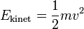
A coil with current stores energy in a magnetic field equal to the work that must be done to establish the current current  . This energy is equal to:
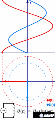
Vector diagram in complex amplitudes for an ideal inductor in a sinusoidal voltage circuit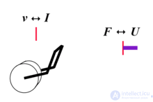
An inductor in alternating voltage is an analog of a body with a mass subject to mechanical vibrations.
 .
.
When the current changes in the coil, an EMF of self-induction occurs, the value of which:
 .
.
For an ideal inductor (without parasitic parameters), the self-induction EMF is equal in magnitude and opposite in sign to the voltage at the ends of the coil:
 .
.
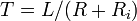
When the coil is closed with a current on the resistor, the current in the circuit decreases exponentially in accordance with the formula:
 ,
,
where:  is the current in the coil,
 - the initial current of the coil,
 - current time
 - time constant.
The time constant is expressed by the formula:
 ,
,
where:  is the resistance of the resistor,
 - ohmic resistance of the coil.
When shorting the coil with current, the process is characterized by its own time constant:  coil:
coil:
 .
.
When tending to zero, the time constant tends to infinity, which is why the current flows “forever” in superconducting circuits.
In a sinusoidal current circuit, the current in the coil lags behind the phase of the voltage across it by π / 2.
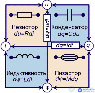
The phenomenon of self-induction is similar to the manifestation of the inertia of bodies in mechanics, if mass is taken as an analog of inductance, current is speed, voltage is force, then many formulas of mechanics and inductance behavior in a circuit take a similar form:
 ↔
↔  where
where
 ↔
↔  ↔
↔  ;
;  ↔
↔  ;
;  ↔
↔
↔ 
The main parameter of an inductor is its inductance, numerically equal to the ratio of the current generated by the magnetic field flux penetrating the coil to the strength of the flowing current. Typical values of coil inductances are from tenths of a microGN to tens of GN.
The inductance of the coil is proportional to the linear dimensions of the coil, the magnetic permeability of the core and the square of the number of turns of the winding. This is evidenced by the site https://intellect.icu. Solenoid coil inductance
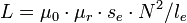 ,
,
where  is the magnetic constant
 - the relative magnetic permeability of the core material (depending on frequency),
 - the cross-sectional area of the core,
 - the length of the midline of the core,
 - the number of turns.
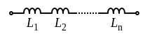
Scheme of series connection of inductors. The current through each coil is the same.
When the coils are connected in series, the total inductance is equal to the sum of the inductances of all connected coils:
 .
.
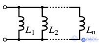
Electric circuit of parallel connection of several inductors. The voltage across all coils is the same
With a parallel connection of the coils, the total inductance is equal to:
 .
.
In the inductor, in addition to the main effect of the interaction of the current and the magnetic field, parasitic effects are observed, as a result of which the impedance of the coil is not purely reactive. The presence of spurious effects leads to the appearance of losses in the coil, estimated by the loss resistance  . Losses consist of losses in wires, dielectric, core and screen:

where  are the losses in the wires,
 - losses in dielectric,
 - core loss,
 Eddy current loss
Losses in wires
Losses in wires are caused by three reasons:
Dielectric loss
Losses in dielectric (insulation of wires and coil frame) can be attributed to two categories:
In the general case, it can be noted that for modern coils of general application, losses in the dielectric are most often negligible.
Core loss
Losses in the core consist of eddy current losses, magnetization reversal losses of a ferromagnet - by “hysteresis”.
Eddy current loss
An alternating magnetic field induces vortex EMF in the surrounding conductors, for example, in the core, shield, and in the wires of adjacent turns. The eddy currents arising in this case (Foucault currents) become a source of losses due to the ohmic resistance of the conductors.
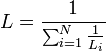
Another characteristic is closely related to loss resistance - quality factor. The quality factor of the inductor determines the relationship between the active and reactance of the coil. Q factor is equal

Vector diagram of losses and quality factors of a real inductor. Designations: Z - impedance; Xc is the capacitive component of the impedance; Xl is the inductive component of the impedance; X is the reactive component of the impedance; Ri is the active component of the impedance.
Sometimes the losses in the coil are characterized by the loss tangent (the reciprocal of the Q factor) - the phase shift of the current and voltage of the coil in the sinusoidal signal circuit relative to π / 2 - for an ideal coil.
Practically, the quality factor lies in the range from 30 to 200. An increase in the quality factor is achieved by an optimal choice of wire diameter, an increase in the size of the inductor and the use of cores with high magnetic permeability and low losses, winding of the universal type, using silver-plated wire, using stranded wire of the form of "litzendrat" to reduce losses caused by the skin effect.
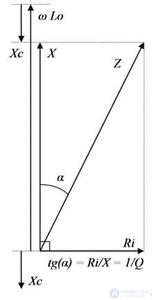
An equivalent circuit and some formulas of a real inductor without a ferromagnetic core
The inter-turn parasitic capacitance of the conductor as part of the inductor turns the coil into a complex distributed circuit. As a first approximation, we can assume that a real coil is equivalently an ideal inductance connected in series with a resistance resistor of a winding with a parasitic capacitor connected in parallel to this circuit (see Fig.). As a result of this, the inductor is an oscillatory circuit with a characteristic resonance frequency. This resonant frequency can easily be measured and is called the natural resonance frequency.inductor coils. At frequencies much lower than the frequency of the intrinsic resonance, the coil impedance is inductive, at frequencies near the resonance it is mostly active (purely active at the resonance frequency) and large in modulus, capacitive at frequencies much higher than the resonance frequency. Typically, the natural frequency is indicated by the manufacturer in the technical data of the industrial inductors, either explicitly or indirectly in the form of the recommended maximum operating frequency.

Dependence of the impedance module and the active component of the impedance on frequency for a real inductor
.
At frequencies below intrinsic resonance, this effect manifests itself in a decrease in the Q factor with increasing frequency.
To increase the frequency of intrinsic resonance, complex schemes of winding coils are used, splitting one winding into spaced sections.
TCI is a parameter characterizing the temperature inductance of a coil.
The temperature instability of the inductance is due to a number of factors: when heated, the length and diameter of the winding wire increases, the length and diameter of the frame increases, as a result of which the pitch and diameter of the turns change; in addition, when the temperature changes, the dielectric constant of the carcass material changes, which leads to a change in the self-capacity of the coil. The influence of temperature on the magnetic permeability of the core ferromagnet is very significant.
The basis for constructing the designations of inductors, chokes, transformers, autotransformers and magnetic amplifiers is the designation of windings, cores, housing, screen, regulation signs, as well as signs indicating the types of connections.
Windings are usually depicted as a circle (Fig. 1.3). The number of semicircles and the direction of the findings is not installed. The designation of the cores is shown in Fig. 1.3, b ... d . Ferromagnetic, ferrite cores (magnetic core) have the designation shown in Fig. 1.3, b , ferromagnetic with an air gap (to prevent saturation of the core from the direct current flowing through the winding) - fig. 1.3, c , magnetodielectric - in Fig. 1.3, g ; however, the number of strokes in the designation is not set. The core, for example, of copper, brass - a non-magnetic material is indicated on the diagrams in accordance with Fig. 1.3, d .
The dimensions of the designation of the inductor are shown in Fig. 1.3, e . Consider the notation in fig. 1.3, g . It includes inductors with taps and a magnetodielectric core adjustable, i.e. the full designation is an inductor with a tap that is tuned by a magnetodielectric core. In fig. 1.3, h shows a single-phase transformer with a fixed core. In fig. 1.3, and shows a single-phase transformer with a ferromagnetic core and a screen between the windings. In fig. 1.3 to given designation single-phase transformer with a ferromagnetic core with three windings. A single-phase autotransformer with a ferromagnetic core is shown in Fig. 1.3, l. In the laboratory autotransformer (LATR), which is widely used in practice, the tap is adjustable.
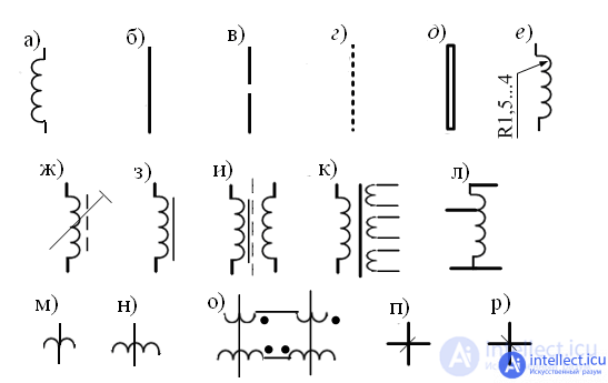
Fig.1.3. Inductors, chokes, transformers, autotransformers and magnetic amplifiers
When depicting magnetic amplifiers, the working winding has the designation shown in Fig. 1.3, m , and the control - in Fig. 1.3, n , where the vertical line indicates the core. A dot is used to indicate the start of the winding. In fig. 1.3, о shows a magnetic amplifier with two serially connected working windings and two counter-connected sections of the control winding. With a large number of windings on the core and a large number of cores in the circuit, the notation fig. 1.3, p, p. In the diagram, the vertical line indicates the core, the horizontal line indicates the electrical connection between the windings, an oblique line indicates the presence of a winding on this core. The end of the oblique line, located under the line, conditionally determines that the connection is made with the beginning of the winding
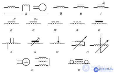
Coil symbols: a) general designation; b) designation of the beginning of the winding with a dot; with a magnetic core (core) c) ferromagnetic, d) with a rectangular hysteresis loop, e) with a non-rectangular hysteresis loop, e) non-magnetic (the chemical formula of the material is indicated), g) with a gap, h) magnetodielectric, and) ferrite; j) with bends; k) adjustable by moving the core, m) adjustable by sliding contact, n) variometer; o) three-phase choke; o) coaxial throttle.
Loop Inductors Used in Radio Engineering
These coils are used in conjunction with capacitors to organize resonant circuits. They must have high thermal and long-term stability, and quality factor, requirements for parasitic capacitance are usually insignificant.
Communication coils, or communication transformers
Magnetic fields interacting with steam and more coils are usually connected in parallel with capacitors for organizing oscillatory circuits. Such coils are used to provide transformer coupling between individual circuits and cascades, which allows dividing by direct current, for example, the base circuit of the subsequent amplification cascade from the collector of the previous cascade, etc. There are no strict requirements for Q factor and accuracy for non-resonant isolation transformers, therefore they are made of thin wire in the form of two windings of small dimensions. The main parameters of these coils are inductance and coupling coefficient (mutual induction coefficient).
Variometers
These are coils whose inductance can be controlled (for example, to tune the resonance frequency of the oscillatory circuits) by changing the relative position of the two coils connected in series. One of the coils is stationary (stator), the other is usually located inside the first and rotates (rotor). There are other designs of variometers. With a change in the position of the rotor relative to the stator, the degree of mutual induction, and hence the variometer inductance, changes. Such a system allows you to change the inductance 4 to 5 times. In ferrovariometers, the inductance is changed by moving the ferromagnetic core relative to the winding, or by changing the length of the air gap of the closed magnetic circuit.
Chokes
These are inductors having high resistance to alternating current and low resistance to direct current. Inductors are connected in series with the load to limit the alternating current in the circuit, they are often used in the power supply circuits of radio devices as a filter element, as well as ballast for connecting discharge lamps to an alternating voltage network. For power networks with frequencies of 50-60 Hz, they are performed on transformer steel cores. At higher frequencies, permalloy or ferrite cores are also used. A special kind of chokes is interference-suppressing ferrite barrels (beads or rings) strung on individual wires or groups of wires (cables) to suppress common-mode high-frequency interference.

Double throttle
Dual chokes
These are two coils of inductance wound in the opposite or matching direction, used in power filters. Due to the counter winding and mutual induction, they are more effective for filtering common-mode noise with the same dimensions. With consonant winding, effective to suppress differential interference. Dual chokes are widely used as input filters of power supplies; in differential signal filters of digital lines, as well as in sound engineering. [2] [3] They are designed both to protect power supplies from getting into them induced high-frequency signals from the supply network, and to prevent penetration into the supply network of electromagnetic interference generated by the device. At low frequencies it is used in power supply filters and usually has a ferromagnetic core (made of transformer steel).To filter high-frequency interference - ferrite core.
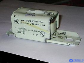
Ballast Choke Design used as reactance for discharge lamps at a frequency of 50 - 60 Hz. Due to the noticeable dependence of the choke resistance on the operating mode and on the frequency spectrum of the current, the choke resistance is defined as the ratio of voltage to current when the lamp is closed and the current through the choke is equal to the lamp operating current. In an electronic ballast for a fluorescent lamp operating at a frequency of 20 - 50 kHz, the inductor is made on a ferrite core and has significantly smaller dimensions.

Comments
To leave a comment
Electronics, Microelectronics, Element Base
Terms: Electronics, Microelectronics, Element Base