Lecture

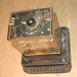


Time relay - a relay designed to create an independent time delay and to ensure a certain sequence of operation of circuit elements. The time relay is used in cases when it is necessary to automatically perform an action not immediately after the appearance of the control signal, but after a set period of time.
Time relays with electromagnetic deceleration are applied only at constant current. In addition to the main winding, relays of this series have an additional short-circuited winding consisting of a copper sleeve. With the increase of the main magnetic flux, it creates a current in the additional winding, which prevents the growth of the main magnetic flux. As a result, the resulting magnetic flux increases more slowly, the time of “breaking off” of the armature decreases, which ensures the time delay when switching on. When the current in the coil is disconnected due to the inductance of the short-circuited coil, the magnetic flux in the relay is retained for some time while holding the armature.
This type of time relay provides a time delay when triggered from 0.07 s to 0.11 s, when disconnected from 0.5 s to 1.4 s.
The time relay with pneumatic deceleration has a special decelerating device - pneumatic damper, cataract. Adjusting the shutter speed is done by changing the cross-section of the air intake, usually with an adjusting screw.
This type of time relay provides a time delay from 0.4 to 180 s, with an accuracy of 10% of the setpoint.
The time relay with the anchor or clockwork works by the spring, which starts up under the action of an electromagnet, and the relay contacts are triggered only after the anchor mechanism counts the time set on the scale. A variety of such relays is used in high-power (for currents of hundreds and thousands of amperes) circuit breakers with a voltage of 0.4-10 kV. The components of such a relay are the deceleration mechanism and the current winding cocking its spring. The speed of the mechanism depends on the spring tightening, that is, on the current in the winding, at the end of the stroke the mechanism causes the automatic switch-off, thereby performing the functions of thermal overload protection, without needing correction in the ambient temperature.
This type of time relay provides a time delay from 0.1 to 20 s with an accuracy of 10% of the installation.
Motor time relays are designed for timing from 10 s to several hours. It consists of a synchronous motor, a gearbox, an electromagnet for coupling and disengaging the motor with a gearbox, contacts.
Before the advent of low-cost microcontrollers, the work of electronic time relays was based on transients in the RC or RL discharge circuit. Modern timers work out the necessary time delay in accordance with the program “wired” into the microcontroller. At the same time, the microcontroller itself can be clocked using an integrated quartz resonator or an RC generator.

Comments
To leave a comment
Electronics, Microelectronics, Element Base
Terms: Electronics, Microelectronics, Element Base