Lecture
If you need to rectify the power with alternating voltage in order to get the full use of both half-periods of the sinusoidal voltage, then you need to use other rectifier circuits. T
Such circuits are called half-wave rectifiers.
One type of half-wave rectifier, called a mid-point rectifier , uses a mid-point transformer in the secondary and two diodes.
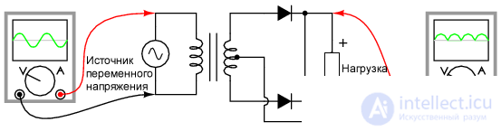
Figure 1 Half-wave rectifier, midpoint circuit
Consider the principle of operation
Let's consider how the circuit works in different halves of the period of sinusoidal stress.
In the first half of the period when the polarity of the source voltage is positive (+) at the top and negative at the bottom.
At this time, only the upper diode conducts current, the lower diode blocks the flow of current, and the load “sees” the first half of the sinusoid, positive at the top and negative at the bottom.
During the first half of the period, current flows only through the upper half of the secondary winding of the transformer.
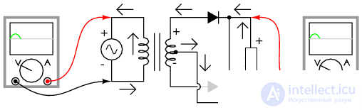
Figure 2 Half-wave rectifier with a midpoint : The upper half of the secondary winding conducts current during the positive half-wave at the input, delivering the positive half-wave to the load (arrows indicate the direction of electron flow)
During the next half-cycle, the polarity of the alternating voltage is reversed. Now the other diode and the other half of the secondary winding of the transformer conduct current, and the part of the circuit that conducted the current during the previous half-cycle is waiting. The load, as before, “sees” half the sinusoid, of the same polarity as before: positive from above and negative from below (see figure below).
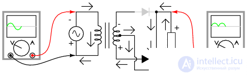
Figure 3 A half-wave rectifier with a midpoint: During the negative half-wave at the input, the current conducts the lower half of the secondary winding, delivering the positive half-wave to the load (arrows indicate the direction of electron flow)
One of the drawbacks of this half-wave rectifier circuit is the need for a mid-point transformer in the secondary winding. This drawback is especially pronounced if a high output power matters to the circuit; the size and cost of a suitable transformer becomes significant. which means that the mid-point rectifier circuit is only used in low power applications.
The polarity at the load of a half-wave rectifier with a midpoint can be changed by changing the direction of the diodes. Also, inverted diodes can be connected in parallel with an existing rectifier with a positive output.
In this way, a bipolar, half-wave rectifier with a midpoint is synthesized, as shown in the figure below.
Please note that the connection of the diodes to each other is similar to the bridge circuit.

Figure 4 Bipolar, half-wave, mid-point rectifier
Summary of the studied
Figure 6

Comments
To leave a comment
Electronics, Microelectronics, Element Base
Terms: Electronics, Microelectronics, Element Base