Lecture
Three Phase Rectifiers
Three-phase AC rectifiers are used as medium and high-power rectifiers. There are two main types of three-phase current rectifiers: a neutral output and a bridge.
Three Phase Neutral Rectifier

Fig. 1 Three-phase neutral output rectifier circuit
Figure 2 shows the time diagrams of the voltage u2 (t) at points a, b, c, the current through the resistor R and the diodes VD1, VD2 and VD3.
The current through the resistor according to the first Kirchhoff law is equal to the sum of the currents of all three branches, taking into account the sign (direction). Since the currents in each phase of this scheme with positive potentials at points a, b, c relative to node d are directed to node d´, the total current through the resistor always has the same direction. Those. current rectification takes place.
We will carry out a more detailed analysis of the three-phase rectification, fig. 2

Fig. 2 Time diagrams of potentials at points a, b, c - ua (t), ub (t), uc (t); currents through the diodes iVD1, iVD2, iVD3 and current through the resistor iR.
At the moment t = 0, the potentials at the points a, c are the same. As a consequence, the potential difference at the terminals of the diodes VD1 and VD3 is zero and therefore the current through these diodes is zero at this moment. The potential at point b with respect to potentials a and c is negative, so the voltage on the pins of the diode VD2 is reverse and the current does not flow through VD2.
When 0> t> t1 on diodes VD2 and VD3, the potential difference corresponds to the reverse voltage, since ua (t)> uc (t)> ub (t), and on VD1 - direct. Therefore, through VD1 and R begins to flow a current equal to.
The maximum current through the resistor will be observed at time t = t1. At t = t2, the potentials at points a and b are equalized and the current through the diodes VD1 and VD2 stops due to a potential difference equal to zero. The current through the diode VD3 is zero due to the fact that the potential at point c is negative and the voltage across it, equal to the potential difference between point c and points a and b, is reverse.
In the intervals from t2 to t3 and from t3 to t4, a similar situation develops for iVD2 and iVD3. The current through the resistor in time consists of a sequence of currents through the diodes VD1, VD2 and VD3.
In a three-phase rectifier with a neutral output, the ripple coefficient is p = 0.25.
The average value of the rectified voltage and current is determined by the following expressions:
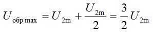
The maximum reverse voltage across the diodes is equal to the potential difference between the points (ac) -b, (ab) -c and (bd) -a at time points t0, t1,  . The potential difference at these points in time on the diodes, respectively, VD1, VD2, VD3 and further is equal to:
A rectifier of this type makes it possible to obtain a rectified current up to hundreds of amperes, with the rectified voltage reaching several tens of kilovolts. The main disadvantage is the magnetization of the transformer core DC, reducing the efficiency of the rectifier
Three Phase Bridge Rectifier
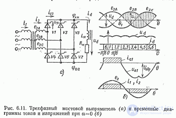
Fig. 3, in all respects exceeds a three-phase rectifier with a neutral output. It is used to convert currents and voltages of medium and high power.
This rectifier contains a bridge of six diodes. In each 1/6 of the period, one of the pairs of diodes is under the action of direct line voltage, while the other four diodes are under the action of reverse voltage.
For example, from t0 until t1, diodes VD1 and VD4 are under direct voltage, since phase a has a positive potential opening VD1 and closing VD2, and phase b has a negative potential opening VD4 diode and blocking VD3. The potential difference between phases a and b during this period is greater than the potential difference between phases a and c and b and c, therefore the diodes VD2, VD3, VD5 and VD6 are locked and do not pass current.
In the next period of time from t1 to t2, the largest linear voltage falls on phases a and c. The potential of phase a holds the diode VD1 and the closed VD2 open, and the negative potential of phase c opens the diode VD6 and closes the diode VD5. The remaining diodes are closed due to the smaller potential difference between phases a and b and b and c.

Fig. 3 Three Phase Bridge Rectifier
and timing diagrams of rectified voltage and currents.
Next, connect the next pair of diodes and turn off the other four. Those. In the corresponding periods of time in the forward direction, the diodes are connected, to which the greatest linear voltage is applied.
It is obvious that the average values of current and voltage for a given rectification circuit are the highest for the considered circuits.

Comments
To leave a comment
Electronics, Microelectronics, Element Base
Terms: Electronics, Microelectronics, Element Base