Lecture
Delay line - a device designed to delay electromagnetic signals for a certain period of time (fixed, switchable or continuously adjustable). Delay lines (hereinafter referred to as Delay line) are widely used in various fields of radio-electronic technologies - in radar and radio navigation, measurement technology, computer technology and automation, electro-acoustics (reverbs), communication technology, and in scientific research
There are Delay line for a delay of electric signals (LF, HF, microwave) and for a delay of optical (light signals)
Delay line are also subdivided into broadband (as a rule, with a lower frequency of 0 Hz) and narrowband (for delaying a superhigh-frequency or optical signal). Microwave and optical lines are dispersive (the wave velocity depends on the frequency) and dispersion free.
TV Delay line
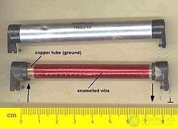
The easiest way to implement electric signal delay is to use transmission lines of a certain length as a delay medium, since the signal propagation speed in lines is finite and relatively stable, the signal passing through a line is delayed by time proportional to its length. Radio frequency cables, strip and microstrip lines, as well as waveguides, mainly ferrite ones (using magnetostatic waves) can be used as the line, the line must have a well-coordinated output load to prevent signal distortion. Historically, the most widespread are cable Delay line - on coaxial cables (used mainly as delay calibrators) and spiral cables (used in oscilloscopes for signal delay relative to the beginning of the sweep and for other purposes). Cable Delay line are simple in the device, reliable, have a small dispersion, broadband (from zero to hundreds of megahertz), the disadvantage is a small delay (fractions of a microsecond, rarely a few microseconds).
Constructive implementation:
Artificial Delay line is a sequence of links that imitate a real line. LC-chains of capacitors, inductive elements or, in some cases (in microwave technology), resonators with distributed parameters can be used as links. Artificial LZs are used for temporal arrangement of pulses in radiolocation devices, radio navigation, for the delay of microwave signals and for other purposes, most often made in the form of modules with multiple taps, which allows obtaining different delay values, there are also LZ with adjustable delay. Artificial LZs make it possible to obtain large delay values than natural lines on cables and waveguides, however, they are inconvenient because they have a small working range, therefore they are gradually replaced by digital LZs in pulsed technology and acoustic ones in microwave technology.
EXAMPLE: LZT-4.0-1200.
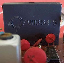
Ultrasonic Delay line on the TV board
The principle of operation of ultrasonic Delay line is that the electrical signal is converted by means of an electromechanical transducer into mechanical collars, which are then propagated by the form of elastic waves in a certain direction through the acoustic duct and then again converted into an electrical signal. The delay time of the output signal relative to the input signal is determined by the acoustic parameters of the sound duct medium, its size and configuration, and the type of waves. Acoustic waves used in Delay line can be of different types and types - surface and volume, transverse (shear waves), longitudinal (compression waves), torsional. By the type of sound conductor used, Delay line are subdivided into waveguide (tape and wire) and, simpler to manufacture, LZ with multiple reflections (with direct course of the beam, coiled, polygonal, wedge-shaped). As electromechanical transducers, usually piezoelectric or magnetostrictive transducers are used. To delay microwave signals, it becomes necessary to transport the input signal spectrum to a lower frequency region, for normal operation of the acoustic part, and then to restore the signal, in this case frequency converters are installed at the input and output, since both converters operate with the same highly stable local oscillator. assume that the spectrum of the output signal is identical to the spectrum of the input signal.
Ultrasonic Delay line have a delay from fractions of a millisecond to tens of milliseconds and are used to delay the chrominance signal in television receivers, as measures of the time interval in measurement technology, as calibrators of distance (height) for radar and radio navigation devices, as memory devices in computing and radar technology for other purposes.
EXAMPLES: LZA-511-10, UL3-64-5, DL872
Digital delay line is a digital device designed to delay digital signals in time for a specified number of cycles. The delay time in such lines is either fixed or can be programmed externally. One line can have several “taps” which allow to obtain a series of signals, each of which will have its own time offset by a specified number of synchronization cycles.
In optical Delay line, light is delayed in the process of passing through an optical medium with a low signal propagation velocity, that is, with a high refractive index. The most common are fiber optic Delay line (similar to cable - for the radio band, there are also LZ in the form of a set of plane-parallel plates of quartz glass (Michelson echelons), based on diffraction gratings and prisms, and prism-lens. To obtain the possibility of using optical delay integrated circuits IBM specialists have developed a model of a fundamentally new Delay line , consisting of a set of consecutive “microcircular resonators,” that is, a kind of artificial line.

Comments
To leave a comment
Electronics, Microelectronics, Element Base
Terms: Electronics, Microelectronics, Element Base