Lecture
Full-Wave Bridge Rectifier with Smoothing Capacitive Filter
Consider a full-wave bridge rectifier with a smoothing capacitive filter Fig.5.
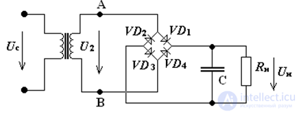
Fig.5 Bridge rectifier circuit with capacitive filter
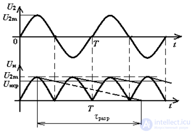
Fig. 6 Timing diagrams of a bridge rectifier with a capacitive filter
From the analysis of the time diagrams (Fig. 4, Fig. 6) it can be seen that with a change in the capacitor C capacitance, the value of the ripple coefficient of the rectified voltage will change. In this case, the less the capacitor is discharged, the less pulsations in the rectified current In will be.
capacitor discharge time constant: τalc = C • Rn.
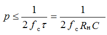
If τrasp >> T, then the ripple coefficient is calculated by the formulas:
for the half-wave scheme:
where: fc is the mains voltage frequency;
for the full-wave scheme:

where: fc is the mains voltage frequency.
To select a capacitor, it is necessary to calculate its capacity and operating voltage.
The capacity of the filter, in the case of small pulsations, is determined by the formula:
for half-wave rectifier
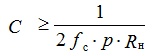
for full-wave rectifier

The operating voltage of the capacitor is calculated with a 30% margin and is:
Urab ≥ 1,3 ∙ U2max
It is necessary to take into account the fact that the produced capacitors have an tolerance on the size of capacitance of ± 12% of the nominal value.
The main parameter characterizing the efficiency of the electric smoothing filter is the smoothing coefficient equal to the ratio of the ripple coefficients at the filter inlet and outlet. When designing filters, the following requirements should be met: the minimum voltage drop across the filter elements, minimum dimensions and weight.
When using a capacitive filter, it should be borne in mind that the maximum value of the current through the diode is determined only by the internal resistance of this element, so it can reach values greater than the maximum allowable values of the forward current of the diode. Such a current can damage the diode. To avoid this, an additional resistor is connected in series to the diode.
If a higher smoothing ratio is required, then more complex LC or RC filters are used. Connecting an inductive coil to a capacitive filter will cause, due to the voltage drop across the coil, the proportion of the variable component of the rectified voltage will significantly decrease, and the voltage drop from the DC component will be almost zero. The problem is only one when using an inductance coil increases the weight and dimensions of the MIHE. Therefore, in MIVA, instead of the inductance Lf, they put a resistor Rf. The filtering effect of Rf is that when Xc << Rn, on Rf there is a greater voltage drop of the variable component of the rectified voltage than a constant.
The smoothing coefficient of the filter in this case will be equal to:

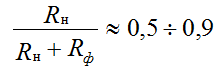
To reduce the constant component was not very large, Rn and Rf choose
commensurate:
If the smoothing filter does not allow to reduce the ripple of the rectified voltage to the desired value, then cascade switching of filters is applied, then the smoothing coefficient is determined by the formula: S = S1 • S2 • S3 • ... Sn

Comments
To leave a comment
Electronics, Microelectronics, Element Base
Terms: Electronics, Microelectronics, Element Base