Lecture
An unstable multivibrator has no stable states . When the multivibrator is on, it simply changes its states by itself after a certain period of time, which is determined by the time constants R C. A DC power supply or V cc is applied to the circuit for its operation.
The two transistors named Q 1 and Q 2 are feedback-coupled to each other. The collector of Q 1 is connected to the base of Q 2 through a capacitor C 1 and vice versa. The emitters of both transistors are connected to ground. The collector load resistors R 1 and R 4 and the bias resistors R 2 and R 3 have the same values. Capacitors C 1 and C 2 have the same value.
The following figure shows a schematic diagram of an unstable multivibrator.
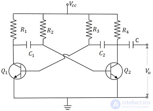
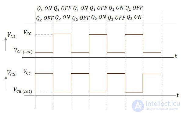
When V cc is applied, the collector current of the transistors increases. Since the collector current depends on the base current,
Since no transistor characteristics are similar, one of the two transistors says that Q 1 has an increase in collector current and therefore conducts. The Q 1 collector is applied to the base from Q 2 to C 1 . This connection allows the increased negative collector voltage of Q 1 to be applied to the base of Q 2 and its collector current decreases. This continuous action causes the collector current of Q 2 to decrease further. This current, when applied to the base Q 1, makes it more negative and with the combined actions of Q 1saturates and Q 2 turns off. Thus, the output voltage of Q 1 will be V CE (sat) and Q 2 will be equal to V CC .
Capacitor C 1 charges through R 1, and when C 1 reaches 0.7 V, that's enough to turn Q 2 to saturation. When this voltage is applied to the base of Q 2 , it saturates, decreasing the collector current. This voltage drop at point B is applied to the base of Q 1 -C 2, which reverse biases Q 1 . This sequence turns off Q 1 and saturates Q 2 . Now point A has a potential V CC . Capacitor C 2 is charged through R 2 . The voltage across this capacitor C 2, when it reaches 0.7 V, turns Q 1 on until it saturates.
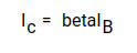
Therefore, the output voltage and the output waveform are generated by alternately switching transistors Q 1 and Q 2 . The time period for these ON / OFF states depends on the values of the bias resistors and capacitors used, ie, the values of R C used . Since both transistors operate alternately, the output signal is a square wave with a peak amplitude of V CC .
The output signals to the Q 1 and Q 2 collectors are shown in the following figures.
The turn- on time of Q 1 or the turn-off time of Q 2 is defined as
t 1 = 0.69R 1 C 1
Similarly, the turn-off time of Q 1 or the turn-on time of Q 2 is defined as
t 2 = 0.69R 2 C 2
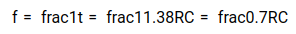
Therefore, the total time period of the square wave is

Since R 1 = R 2 = R and C 1 = C 2 = C, the frequency of the square wave will be
The advantages of using an unstable multivibrator are as follows:
The disadvantages of using an unstable multivibrator are as follows:
Unstable multivibrators are used in many applications such as hobby radio equipment, Morse code generators, timer circuits, analog circuits, and television systems.

Comments
To leave a comment
Electronics, Microelectronics, Element Base
Terms: Electronics, Microelectronics, Element Base