Lecture
As mentioned in the previous section, most modern digital devices are sequential or digital automata with memory, consisting of a combinational circuit and memory elements - storage elements (GE) (Fig.4.1). There have been reviewed
the simplest digital elements, which include the trigger, registers, counters, and clock allocators. The simplest digital devices can be easily synthesized using the logical and digital elements considered. More complex digital devices, called digital nodes, are more conveniently viewed and designed from more general positions using the theory of digital automata.
Under the digital automatic (CA) understand the device designed to convert discrete information. From a general point of view, the process of obtaining information is nothing but a process of removing uncertainty as a result of the fact that a phenomenon actually occurred takes place from a certain aggregate of possible phenomena in a given specific situation.
The structure of digital machines necessarily includes storage elements (memory elements). The output signals in such machines are formed depending on the input signals and the states in which the memory elements are located. The presence of memory elements makes it an object for the TsA to have some internal state A , determined by the set of states of all memory elements. Depending on the internal state of the central part, they react differently to the same set of input signals. Perceiving the input signals Z at a certain state, the central arc, in accordance with the program embedded in it, enters a new state and produces output signals W. Transitions of a CA from one state to another begin with some initial state, the task of which is also part of the task of the automaton. Ultimately, the current state and outputs of the automaton depend on the initial state and all sets of input signals received on the automaton at previous points in time. Thus, the entire sequence of input signals determines the sequence of states of the automaton and its output signals. This explains the name "sequence diagrams."
The main quality that distinguishes digital automata from among all other information converters is the presence of a discrete set of internal states and the property of an automaton hopping from one state to another. A jump jump means the ability to treat this transition as instantaneous, although for any real automaton there is a finite duration of transients, so the requirement for a jump jump is not satisfied.
The second assumption is that after the transition of the automaton to an arbitrary state, the transition to the next state is possible no earlier than after a certain fixed time interval for this automaton τ> 0, the so-called discrete interval of the automaton. This assumption makes it possible to consider the operation of a digital automaton in discrete time . When building automata with discrete automaton time, we distinguish between synchronous and asynchronous automata.
Digital automata in the canonical representation are divided into two parts (Fig. 5.1): memory (EP) and combination circuit (CC). At the inputs of the CC are input signals Z t and status signals A t of the digital automat. At its output, the output signals W t and the signals transferring the central signal to the new state A t +1 are produced.
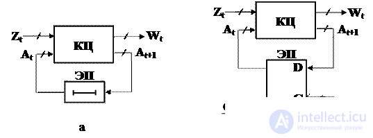
Fig. 5.1. Block diagram of asynchronous (a) and synchronous (b) digital automata
In asynchronous machines (Fig. 5.1.a) , the role of memory elements is often played by delay elements, through which the state signals A t are transmitted to the CC inputs, so that together with the new set of input variables Z t determine the next pair of output values W t and the state A t +1 at the exit. Elements of the asynchronous central Asian switch under the direct influence of changes in input signals. The speed of propagation of the switching process in the circuits of an asynchronous automaton is determined by the intrinsic delays of the elements; therefore, the moments of transitions from one state to another are not predetermined and can occur through unequal intervals of time.
In synchronous machines there are special inputs C for the supply of clock signals that allow memory elements to receive data only at certain points in time. The elements of memory (EP) in these machines are synchronous triggers . The moments of time at which it is possible to change the state of the automaton are determined by a special device — a generator of synchronizing pulses , the output of which is connected to the input C of the synchronous automaton. The neighboring moments of time are usually divided by equal time intervals. The processing of information in synchronous ACs is ordered in time, and within one cycle it is possible to spread the switching process only within strictly defined limits of the information processing path.
The general theory of automata under the assumptions made above is divided into two large parts, which are given the names of the abstract theory of automata and the structural theory of automata . The difference between them lies in the fact that the abstract theory does not take into account the structure of both the automaton itself and the structure of its input and output signals. In this case, input and output signals are considered simply as letters of two alphabets fixed for a given automaton: input and output. Not interested in the method of constructing the automaton, the abstract theory studies only those transitions that the automaton undergoes under the influence of input signals and the output signals that it produces.
In contrast to the abstract theory, the structural theory of automata takes into account the structures of the automaton and its input and output signals. Structural theory studies methods for constructing automata from several elementary automata, methods for encoding input and output signals by elementary signals transmitted over real input and output channels.
Thus, the structural theory of automata is a continuation and further development of the abstract theory. In particular, the task of synthesizing an idealized (disregarding transient) digital automaton is naturally divided into stages of abstract and structural synthesis .
The mathematical model of CA (in the general case of any discrete device) is the so-called abstract automaton defined as a 6-component tuple: S = (A, Z, W, d, l, and 1 ) which:
1. A = {a 1 , a 2 , ..., a m } is the set of states (inner alphabet),
2. Z = {z 1 , z 2 , ..., z f } is the set of input signals (input alphabet),
3. W = {w 1 , w 2 , ..., w g } is the set of output signals (output alphabet),
4. d : A · Z®A is a transition function that implements the mapping D d Í A · Z to A. In other words, the function d for some pairs of “state - input signal” (a m , z f ) associates the states of the automaton with s = d (a m , z f ), a s Î A,
5. l : A · Z®W is a function of the outputs that implements the mapping D l Í A · Z to W. The function l for some pairs of “state - input signal” (a m , z f ) associates the output signals of the automaton W g = l (a m , z f ), W g Î W,
6. a i Î A is the initial state of the automaton.
The alphabet here means a non-empty set of pairs of different characters. Elements of the alphabet are called letters , and the final ordered sequence of letters is a word in a given alphabet.
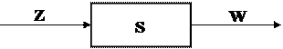
Fig. 5.2. Abstract machine
An abstract automaton (Fig. 5.2) has one input and one output. The automaton operates in discrete time, taking integer non-negative values t = 0, 1, 2, ... At each time t of discrete time, the automaton is in a certain state a (t) from the set of automaton states, and at the initial time t = 0 it is always is in the initial state a (0) = a1. At time t, being in the state a (t), the automaton is able to receive the input alphabet letter z (t) Î Z. In accordance with the function of the outputs, it will issue at the same time t the letter of the output alphabet W (t) = l ( a (t), z (t)) and in accordance with the transition function will move to the next state a (t + 1) = d [a (t), z (t)], a (t) Î A, w (t ) Î W.
The meaning of the concept of an abstract automaton is that it implements some mapping of the set of words of the input alphabet Z into the set of words of the output alphabet W. That is, if a certain sequence of letters of the input alphabet z (0), z (1), ... is input to the input of the automaton set to the initial state a1, letter by letter, then the output alphabet of the output alphabet w (0 ), w (1), ... is the output word. Thus, the output word = = j (input word), where j is the mapping performed by the abstract automaton.
At the level of abstract theory, the concept of "automaton operation" is understood as the transformation of input words into weekend words. We can say that in the abstract machine we digress from its structure - the contents of the rectangle (Fig. 5.1), considering it as a “black box”, i.e. We focus on the behavior of the automaton relative to the external environment.
The concept of state in the definition of an automaton is introduced in connection with the fact that it is often necessary to describe the behavior of systems whose outputs depend not only on the state of the inputs at a given time, but also on some historical background, i.e. from signals that came to the inputs of the system earlier. States just correspond to some memory of the past, allowing you to eliminate time as an explicit variable and express the output signal as a function of state and input at a given point in time.
In practice, the most widespread are two classes of automata, the Mealy and Moore automata.
The law of functioning of the Miles automaton is given by the equations:
a (t + 1) = d (a (t), z (t)); w (t) = l (a (t), z (t)), where t = 0,1,2, ...
The law of operation of Moore’s automaton is given by the equations:
a (t + 1) = d (a (t), z (t)); w (t) = l (a (t)), where t = 0,1,2, ...
Comparison of the laws of operation shows that, unlike the Mile automaton, the output signal in Moore’s automaton depends only on the current state of the automaton and does not explicitly depend on the input signal. To complete the job of the Mile or Moore machine, in addition to the laws of operation, you must specify the initial state and define the internal, input and output alphabets.
In addition to the Mily and Moore automata, it sometimes turns out to be convenient to use the combined automaton model, the so-called C-automaton.
An abstract C-automaton is a mathematical model of a discrete device defined by an eight-component vector.
S = (A, Z, W, U, d, l 1 , l 2 , and 1 ), in which:
1. A = {a 1 , a 2 , ..., a m } is the set of states;
2. Z = {z 1 , z 2 , ..., z f } is the input alphabet;
3. W = {w 1 , w 2 , ..., w g } is the output alphabet of type 1;
4. U = {u 1 , u 2 , ..., u h } is the output alphabet of type 2;
5. d : A · Z ® A is a transition function that implements the mapping D d Í A · Z to A;
6. l 1 : A · Z ® W is the output function that implements the mapping D l 1 Í A · Z to W;
7. l 2 : A ® U is a function of the outputs that implements the mapping D l 2 Í A to U;
8. a 1 Î A is the initial state of the automaton.
An abstract C-automaton can be represented as a device with one input, which receives signals from the input alphabet Z, and two outputs that receive signals from the alphabets W and U. The difference between the C-automaton and Mile and Moore models is that It simultaneously implements two functions of the outputs l 1 and l 2 , each of which is characteristic of these models separately. The law of the C-automaton functioning can be described by the following equations: a (t + 1) = d (a (t), z (t)); w (t) = l 1 (a (t), z (t)); u (t) = l 2 (a (t)) , where t = 0, 1, 2, ...
The output signal U h = l 2 (a m ) is given all the time while the machine is in the state a m . The output signal Wg = l 1 (a m , z f ) is given when the input signal Z f is in effect when the automaton is in the state a m .
The above abstract automata can be divided into:
1) fully defined and partial;
2) deterministic and probabilistic.
An abstract digital automaton is called completely defined , in which the transition function and output function are defined for all pairs (a i , z j ).
Partial is an abstract automaton whose transition function or exit function, or both, are not defined for all pairs (a i , z j ).
The deterministic ones are automata that have the uniqueness condition for transitions: an automaton that is in a certain state a i , under the action of any input signal z j cannot go into more than one state.
Otherwise, it will be a probabilistic automaton in which, with a given state a i and a given input signal z j , a transition with a given probability to various states is possible.
An abstract automaton is called finite if the sets A = {a 1 , a 2 , ..., a m }, Z = {z 1 , z 2 , ..., z f }, W = {w 1 , w 2 , ..., w g }. The automaton is called initial if it contains the initial state a 1 .
Following the stage of abstract synthesis of automata, there follows a stage of structural synthesis , the purpose of which is to construct a circuit that implements an automaton from elements of a given type. If the abstract automaton was only a mathematical model of the projected device, then the structural automaton takes into account the structure of the input and output signals of the automaton, as well as its internal structure at the level of logic circuits. The main task of the structural theory of automata is the development of general methods for constructing structural schemes of automata.
Unlike an abstract automaton having one input and one output (Fig. 5.3.a), which receive signals in the input and exit in the output W = {W 1 , .., W G } alphabets, structural automaton (Fig. 5.3 .b) has L input channels x 1 , x 2 , .., x L and N output y 1 , y 2 , ..., y N on each of which a structural alphabet signal is present.
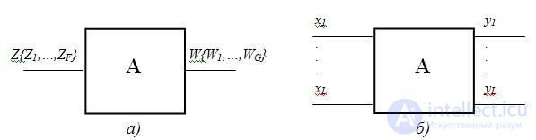
Fig.5.3. Abstract (a) and structural (b) automata
Usually the binary alphabet is used as a structure. In this case, each input signal Z F of the abstract automaton corresponds to a binary vector (l f1 , l f2 , .., l fL ) , where l fL Î {0,1}.
Obviously, to represent (coding) the input signals Z 1 , .., Z F of an abstract automaton by different binary vectors, the condition L must be satisfied  ] log 2 F [ , similar to N ] log 2 G [ . For example, Z = {Z 1 , Z 2 , Z 3 , Z 4 } and W = {W 1 , W 2 , W 3 } , then L log 2 4 = 2 and N log 2 3 = 2
You can code input and output signals, for example, like this: Z 1 = 00, Z 2 = 01, Z 3 = 10, Z 4 = 11, W 1 = 00, W 2 = 01 and W 3 = 11.
Consequently, a structural automaton with two inputs x 1 and x 2 and two outputs y 1 and y 2 can be represented as shown in Fig. 5.4:

Fig.5.4 Structural automaton with two inputs x 1 and x 2 and two
outputs y 1 and y 2
In order to specify an automaton, it is necessary to describe all components of the tuple S = (A, Z, W, d, l, and 1 ). Sets A, Z, W are described and specified by a simple listing of their elements. Among the variety of different ways of setting the functions d and l (and hence of the entire machine as a whole), tabular and graphical are the most common .
In the tabular method of the job, the Miles machine is described using two tables. One of them ( transition table ) defines the function d, i.e. a (t +1) = d (a (t), z (t)) (Table 5.1), the second ( output table ) is the function l, i.e. W (t) = l (a (t), z (t)) (Table 5.2).

Each column of the tables listed corresponds to one state from the set A, each row contains one input signal from the set Z. At the intersection of the column a m and the line z f in the table. 5.1, the state a s is written to which the automaton should go from state a m under the action of the input signal Z f , i.e a s = d (a m , z f ). At the intersection of the column a m and the rows z f in table. 5.2 the output signal W g is written out by the machine in the state a m when the signal z f arrives at the input, i.e. W g = l (a m , z f ).
For the above tables, the sets forming the automaton A = {a 1 , a 2 , a 3 , a 4 }, Z = {z 1 , z 2 }, W = {w 1 , w 2 , w 3 , w 4 , w 5 }. The Miles machine can be defined by one combined table of transitions and exits (Table 5.3), in which each element a s / w g written at the intersection of column a m and line z f is defined as follows: a s = d (a m , z f ); w f = l (a m , z f ) .

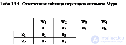
Moore's automaton is defined by one marked transition table (Table 5.4), in which not only the state a m is assigned to each column, but also the output signal W g corresponding to this state, where W g = l (a m ).
For partial Mily and Moore automata in the considered tables, a dash is put at the place of uncertain states and output signals. In such automata, the output signal at any transition is always undefined if the transition state is uncertain. In addition, the output signal may be undefined for some existing transitions.
The table method is also used for specifying C - automata. В этом случае таблица переходов (табл.5.5) аналогична таблице переходов автомата Мили, а в таблице выходов каждое состояние отмечено соответствующим выходным сигналом u i выходного алфавита типа 2 (табл.5.6).
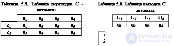
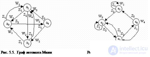
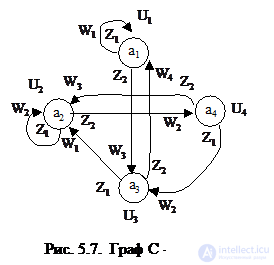
При графическом способе автомат задается в виде ориентированного графа , вершины которого соответствуют состояниям, а дуги - переходам между ними. Дуга, направленная из вершины a m , задает переход в автомате из состояния a m в состояние a s . В начале этой дуги записывается входной сигнал Z f ÎZ, вызывающий данный переход a s =d(a m ,z f ). Для графа автомата Мили выходной сигнал w g ÎW, формируемый на переходе, записывается в конце дуги, а для автомата Мура – рядом с вершиной a m , отмеченной состоянием a m , в котором он формируется. Если переход в автомате из состояния a m в состояние a s производится под действием нескольких входных сигналов, то дуге графа, направленной из a m в a s , приписываются все эти входные и соответствующие выходные сигналы. Граф С-автомата содержит выходные сигналы двух типов и они обозначаются на графе как на графах соответствующих автоматов. Графы автоматов, заданных своими таблицами переходов и выходов (табл. 5.1¸5.6) представлены на рисунках 5.5¸5.7.
Автоматы Мура, Миля и С-автоматы определяют лишь структуру построения автомата. Автоматы, имеющие разную внутреннюю структуру, могут быть эквивалентны. Два автомата с одинаковыми входными и выходными алфавитами называются эквивалентными, если после установки их в начальное состояние их реакции на любое входное слово совпадают.
|
|
Для каждого автомата Мили может быть построен эквивалентный ему автомат Мура и наоборот .( аналогично это относится и к С-автоматам)
Переход от автомата Мура к эквивалентному ему автомату Мили тривиален и легко осуществляется при графическом способе задания автомата. Для получения графа автомата Мили необходимо выходной сигнал W g , записанный рядом с вершиной a s исходного автомата Мура, перенести на все дуги, входящие в эту вершину.
Легко убедиться, что полученный автомат Мили действительно эквивалентный исходному автомату Мура. Для этого достаточно рассмотреть реакцию обеих автоматов на произвольную входную последовательность. Необходимо также отметить, что в эквивалентном автомате Мили количество состояний такое же, как и в исходном автомате Мура.
Переход от автомата Мили к эквивалентному ему автомату Мура более сложен. Это связано с тем, что в автомате Мура в каждом состоянии вырабатывается только один выходной сигнал. Переход наиболее наглядно делать при графическом способе задания автомата. В этом случае каждое состояние a i исходного автомата Мили порождает столько состояний автомата Мура, сколько различных выходных сигналов вырабатывается в исходном автомате при попадании в состояние a i . Рассмотрим переход от автомата Мили S a к автомату Мура S b на примере автомата (рис. 5.6).
Как следует из рис. 5.6, для автомата S a при попадании в состояние а 1 вырабатываются выходные сигналы W 2 , W 4 , W 5 , при попадании в а 2 – W 1 , W 2 , a 3 – W 2 , a 4 – W 3 . Каждой паре „состояние a i - выходной сигнал W j ”, который вырабатывается при попадании в это состояние, поставим в соответствие состояние b k эквивалентного автомата Мура S b с тем же выходным сигналом W j : b 1 =(a 1 , W 2 ), b 2 =(a 1 , W 4 ), b 3 =(a 1 , W 5 ), b 4 =(a 2 , W 1 ), b 5 =(a 2 , W 2 ), b 6 =(a 3 , W 2 ), b 7 =(a 4 , W 3 ), т.е. каждое состояние a i автомата Мили порождает некоторое множество A i состояний эквивалентного автомата Мура: A 1 ={b 1 , b 2 , b 3 }, A 2 ={b 4 , b 5 }, A 3 ={b 6 }, A 4 ={b 7 }. Как видно, в эквивалентном автомате Мура количество состояний 7. Для построения графа S b поступаем следующим образом. Because в автомате S a есть переход из состояния а 1 в состояние а 2 под действием сигнала z 1 с выдачей W 1 , то из множества состояний A 1 = {b 1 , b 2 , b 3 }, порождаемых состоянием а 1 автомата S a в автомате S b должен быть переход в состояние (a 3 , W 2 ) = b 6 под действием сигнала Z 2 и т.д. Граф эквивалентного автомата Мура представлен на рис. 5.8.
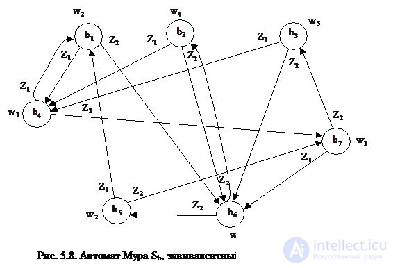
Если от автомата Мура S b , эквивалентного автомату Мили S a (рис. 5.8) вновь перейти к автомату Мили, то получим автомат Мили S 1 (рис. 5.9).
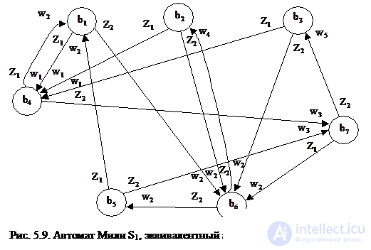
Вследствие транзитивности отношения эквивалентности два автомата Мили S 1 и S a также будут эквивалентными, но у последнего будут на 3 состояния больше. Таким образом, эквивалентные между собой автоматы могут иметь различное число состояний, в связи с чем возникает задача нахождения минимального (т.е. с минимальным числом состояний) автомата в классе эквивалентных между собой автоматов.
Рассмотрим метод минимизации полностью определенных автоматов, предложенный Ауфенкампом и Хоном.
Основная идея этого метода заключается в разбиении всех состояний исходного абстрактного автомата на попарно непересекающиеся классы эквивалентных состояний и замене каждого класса эквивалентности одним состоянием. So получающийся в результате минимальный автомат имеет столько состояний, на сколько классов эквивалентности разбиваются состояния исходного автомата.
Для пользования методом введем несколько определений.
Два состояния абстрактного автомата называются 1-эквивалентными в том случае, если реакции автомата в этих состояниях на всевозможные входные слова совпадают.
Объединение всех 1-эквивалентных состояний абстрактного автомата образует 1-класс эквивалентности.
1-эквивалентные состояния автомата называются 2-эквивалентными, если они переводятся любым входным сигналом также в 1-эквивалентные состояния.
Объединение всех 2-эквивалентных состояний образует 2-класс эквивалентности.
По индукции можно распространить определение до i-эквивалентных состояний и i-классов эквивалентности.
Если для некоторого i разбиения состояний автомата на ( i +1) - классы совпадает с разбиением на i-классы, то оно является разбиением и на ¥ - классы эквивалентности.
Разбиение множества внутренних состояний автомата на ¥ - классы и является требуемым разбиением на классы эквивалентности, при этом такое разбиение может быть получено за конечное число шагов.
Все вышеизложенное непосредственно применимо к минимизации автомата Мили. При минимизации полностью определенных автоматов Мура вводится понятие 0-эквивалентности состояний и разбиение множества состояний на 0-эквивалентные классы: к такому классу относятся одинаково отмеченные состояния автомата Мура.
Если два 0-эквивалентных состояния любым входным сигналом переводится в два 0-эквивалентных состояния, то они называются 1-эквивалентными. Все дальнейшие классы эквивалентности состояний для автомата Мура определяются аналогично приведенному для автоматов Мили.
Рассмотрим пример минимизации автомата Мили, заданного таблицами переходов и выходов – таблицы 5.7.
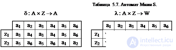
Из таблицы выходов получаем разбиение на 1-классы эквивалентности p 1 , объединяя в эквивалентные классы Bi состояния с одинаковыми столбцами: p 1 = {B 1 , B 2 }; B 2 = {a 1 , a 2 , a 5 , a 6 }; B 2 = {a 3 , a 4 }. Для получения 2-эквивалентных состояний строим таблицу 1-разбиения (табл.5.8), заменяя в таблице переходов состояния a 1 соответствующими классами эквивалентности B1 или B2.
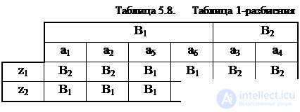
Из полученной таблицы 1-разбиения получаем 2-классы эквивалентности C i и разбиение p 2 = {C 1 , C 2 , C 3 }, где С 1 = {a 1 , a 2 }, C 2 = {a 5 , a 6 }, C 3 = {a 3 , a 4 }. Сравнивая p 2 и p 1 , отмечаем, что эти разбиения отличаются друг от друга. Поэтому аналогично строим таблицу 2-разбиения (табл. 5.9), опять заменяя в таблице переходов состояния a i соответствующими классами эквивалентности C i .

Из полученной таблицы 2-разбиения получаем 3-классы эквивалентности D i и разбиение p 3 ={ D 1 , D 2 , D 3 }, где D 1 = {a 1 , a 2 }, D 2 = {a 5 , a 6 }, D 3 = {a 3 , a 4 }.
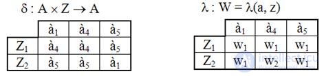
Сравнивая p 3 и p 2 , замечаем, что D 1 = C 1 , D 2 = C 2 , D 3 = C 3 , p 3 = p 3 . Следовательно получили разбиение на ¥- эквивалентные классы. Because всего три таких класса, то минимальный автомат будет содержать всего три состояния. Выбираем из каждого класса D i по одному состоянию и получаем множество состояний A' минимального автомата. Пусть, например, A'={à 1 , à 4 , à 5 }. Для получения минимального автомата из первоначальных таблиц переходов и выходов (табл. 5.7) вычеркиваем столбцы, соответствующие "лишним состояниям" a 2 , a 3 , a 6 . В результате получается минимальный автомат Мили, эквивалентный исходному автомату (табл. 5.10).
Табл.5.10. Таблицы переходов и выходов минимального автомата
Минимизацией числа внутренних состояний автомата заканчивается этап абстрактного синтеза.
ЭВМ перерабатывает информацию, выполняя над ней какие-то операции. Для выполнения операций над информацией используются операционные устройства – процессоры, каналы ввода-вывода, устройства управления внешними устройствами и т.д. Функцией операционного устройства является выполнение заданного множества операций F ={ f 1 ,..., f G } над входными словами D ={ d 1 ,..., d H } c целью вычисления слов R ={ r 1 ,..., r Q }, которые представляют результаты операций R = f g ( D ), где g =1,2,..., G .
Функциональная и структурная организация операционных устройств базируется на принципе микропрограммного управления, который состоит в следующем:
1. Любая операция f g ( g =1,..., G ), реализуемая устройством, рассматривается как сложное действие, которое разделяется на последовательность элементарных действий над словами информации. Эти элементарные действия называются микрооперациями .
2. Для управления порядком следования микроопераций используются логические условия , которые в зависимости от значений слов, преобразуемых микрооперациями, принимают значения " ложь " или " истина " (1 или 0).
3. Процесс выполнения операций в устройстве описывается в форме алгоритма, который представляется в терминах микроопераций и логических условий и называется микропрограммой . Микропрограмма определяет порядок проверки значений логических условий и следования микроопераций, необходимый для получения требуемых результатов.
4. Микропрограмма используется как форма представления функции устройства, на основе которой определяется структура и порядок функционирования устройства во времени.
Таким образом, из принципа микропрограммного управления следует, что структура и порядок функционирования операционных устройств предопределяется алгоритмом выполнения операции F ={ f 1 ,..., f G }.
К элементарным действиям над словами информации - микрооперациям относятся: передача информации из одного регистра в другой, взятие обратного кода, сдвиг и т.д.
В любом устройстве обработки цифровой информации можно выделить два основных блока – операционный автомат (ОА) и управляющий автомат (УА).
Операционный автомат (ОА) служит для хранения слов информации, выполнения набора микроопераций и вычисления значений логических условий X (рис. 5.10), т.е. операционный автомат является структурой, организованной для выполнения действий над информацией. Микрооперации, выполняемые ОА, задаются множеством управляющих сигналов Y ={ y 1 ,...., y M }, с каждым из которых отождествляется определенная микрооперация.
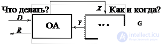
Fig. 5.10. Структурная операционного устройства с микропрограммным управлением
Значения логических условий, вычисляемые в операционном автомате, отображаются множеством осведомительных сигналов X ={ x 1 ,..., x L }, каждый из которых отождествляется с определенным логическим условием.
Управляющий автомат (УА) генерирует последовательность управляющих сигналов, предписанную микропрограммой и соответствующую значениям логическим условий. Иначе говоря, управляющий автомат задает порядок выполнения действий в ОА, вытекающий из алгоритма выполнения операций. Наименование операции, которую необходимо выполнить в устройстве, определяется кодом g операции, поступающим в УА извне. По отношению к УА сигналы g 1 ,..., g h , посредством которых кодируется наименование операции и осведомительные сигналы x 1 ,..., x L , формируемые в операционном автомате, играют одинаковую роль: они влияют на порядок выработки управляющих сигналов Y. Поэтому сигналы g 1 ,..., g h и x 1 ,..., x L относятся к одному классу – к классу осведомительных сигналов, поступающих на вход УА.
So любое операционное устройство – процессор, канал ввода-вывода и т.д. – является композицией операционного и управляющего автоматов. Операционный автомат, реализуя действия над словами информации, является исполнительной частью устройства, работой которого управляет управляющий автомат, генерирующий необходимые последовательности управляющих сигналов.
Операционный и управляющий автоматы могут быть определены своими функциями – перечнем выполняемых ими действий.
Функция ОА определяется следующей совокупностью сведений:
1) множеством входных слов D ={ d 1 ,..., d H }, вводимых в автомат в качестве операндов;
2) множеством выходных слов R ={ r 1 ,..., r Q }, представляющих результаты операций;
3) множеством внутренних слов S ={ s 1 ,..., s N }, используемых для представления информации в процессе выполнения операций. Можно считать, что входные и выходные слова совпадают с определенными внутренними D ÍS, RÍS.
4) множеством микроопераций Y ={ y m }, реализующих преобразование S = j m ( s ) над словами информации, где j m – вычисляемая функция;
5) множеством логических условий X ={ x i }, где x i = y i ( s i ) и y i – булева функция;
To функция ОА задана, если заданы (определены) множества D , R , S , Y , X . Время не является аргументом функции ОА. Функция устанавливает список действий-микроопераций и логических условий, которые может выполнять автомат, но никак не определяет порядок следования этих действий во времени. Those. функция ОА характеризует средства, которые могут быть использованы для вычислений, но не сам вычислительный процесс.
Порядок выполнения действий во времени определяется в форме функций управляющего автомата.
The function of the controlling automaton is an operator scheme of the algorithm (microprogram), whose functional operators are the symbols y 1 , ..., y m , identified with microoperations, and Boolean variables x 1 , ..., x L are used as logical conditions. Those. the set of micro-operations, united by the operation algorithm, constitutes the operation microprogram, which, in turn, is the link between the command (operation code) and the operating device (hardware) intended for information conversion.
The control machine consists of separate logic circuits that generate control signals in a given sequence. Such an automaton can be considered as a Moore or Mile control automaton.
To build a control circuit of the machine, you need to set the firmware of the operating device. The firmware is most often represented as a graph - algorithm diagram (GSA). The GAW determines the computational process sequentially in time, setting the order of checking the logical conditions x 1 ÷ x L and the order of micro-operations at 1 ÷ y m .
According to the principle of firmware management, any complex operation is divided into a number of micro-operations that are performed by OA. Various micro-operations are performed by elementary OA - the so-called operational elements (OE), which are the constituent parts of the main OA.
Under the operational element understand the device that implements one of the following functions or their arbitrary combination :
- storing word information;
- performance of some micro-operations, as a result of which a new value of a word is calculated;
- calculations of the logical condition depending on the word.
It is considered that the OE function is defined if:
- description of the stored or calculated word;
- A description of the many micro-operations performed by this element;
- description of the logical conditions calculated by this element.
To build OA, OE are interconnected with the help of information word transfer circuits from the outputs of some elements to the inputs of others.
Depending on the performed micro-operations, OEs are divided into types: bus, register, counter, adder, comparison circuit, decoder, encoder, etc.
Algorithm. There are several definitions of this concept. We will adhere to the following: algorithm - a certain sequence of actions, which allows to obtain the desired result in a finite number of steps.
Graph diagram of the algorithm (GSA). The GSA allows to describe the sequence of the steps of the algorithm in general form as a graphical notation, without going into details of the implementation of this algorithm. So The flowchart of the algorithm is a form of representation of the microprogram that the operational device (OU) must perform. When constructing an operational device, as consisting of an operational (OA) and control (UA) automata, it is necessary to be able to distinguish the OA and UA functions from the GSA. Usually, the firmware is presented as a meaningful GSA. In this case, in order to set the OA functions, it is necessary to list all the performed micro-operations and all the checked logical conditions of this firmware, as well as to describe the word width processed by the operating device. To initiate the execution of a micro-operation, OA should receive the control signals Yi at the time point required by GSA. Usually, when designing OU, they accept a certain method of coding micro-operations (most often, a code containing as many digits as many different micro-operations) and, for developing OA, they consider that the OA issues the code of micro-operations that must be executed at a given time.
For UA, the sequence of issuing the corresponding micro-operation codes is important, depending on the logical conditions produced by the OA and
analyzed UA at the right time. If the micro-operation coding method is adopted, then the UA functions are set by the coded GSA. Therefore, for different content GAW, having the same coded GAW, OA will be different, but the AA will be the same.
In addition to its visibility, the GSA makes it possible to use effective methods of graph theory for analyzing and transforming microprograms. In the graphic description, the individual functions of the algorithms (micro-operations) are displayed in the form of conventional graphic images - vertices . In GAW, vertices of the following types are commonly used:
 - the top “ beginning ” has one exit, has no inputs. Indicates the beginning of the firmware.
 - the “ end” vertex has any number of inputs, it has no outputs. Indicates the end of the firmware.
 - the operator vertex has any number of inputs and one output. Inside the operator vertex, one microinstruction is recorded — a set of microoperations that allow for joint (ie, simultaneous) execution.
 - a conditional vertex has any number of inputs and 2 outputs. Inside the conditional vertex, a Boolean expression is written, depending on the value of which the direction of the further execution of the firmware is selected.
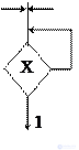 - a special kind of conditional vertex - waiting , has a set of inputs, 2 outputs, one of which is attached to the input. When hitting
продолжение следует...
Часть 1 Topic 5. Digital nodes circuit design
Часть 2 5.8. Abstract synthesis of Mile and Moore firmware control automata

Comments
To leave a comment
Computer circuitry and computer architecture
Terms: Computer circuitry and computer architecture