Lecture
A cluster is two or more computers (often called nodes) that are combined using network technologies based on bus architecture or a switch and appear to users as a single information and computing resource. Servers, workstations, and even ordinary personal computers can be selected as cluster nodes. The node is characterized by the fact that it runs the only copy of the operating system. The advantage of clustering to improve performance becomes obvious in the event of a failure of a node: while the other node of the cluster can take over the load of the failed node, and users will not notice interruptions in access. The scalability of clusters allows you to multiply the performance of applications for more users of technologies (Fast / Gigabit Ethernet, Myrinet) based on the bus architecture or switch. Such supercomputer systems are the cheapest because they are assembled on the basis of standard component parts ("off the shelf"), processors, switches, disks, and external devices.
Clustering can be carried out at different levels of the computer system, including hardware, operating systems, utility programs, control systems and applications. The more levels of the system combined cluster technology, the higher the reliability, scalability and manageability of the cluster .
Conditional class division proposed by Yazek Radaevsky and Douglas Edline:
As already noted, clusters can exist in different configurations. The most common types of clusters are:
Note that the boundaries between these types of clusters are blurred to some extent, and a cluster can have properties or functions that go beyond the listed types. Moreover, when configuring a large cluster used as a general purpose system , it is necessary to allocate blocks that perform all the listed functions.
Clusters for high-performance computing are designed for parallel calculations. These clusters are usually collected from a large number of computers. The development of such clusters is a complex process, requiring at each step the coordination of such issues as installation, operation and simultaneous management of a large number of computers, technical requirements for parallel and high-performance access to the same system file (or files) and interprocessor communication between nodes, and coordination work in parallel mode. These problems are most easily solved by providing a single operating system image for the entire cluster . However, to implement such a scheme is not always possible and usually it is used only for not too large systems.
Multi-threaded systems are used to provide a single interface to a number of resources that can be arbitrarily increased (or reduced) over time. A typical example would be a group of web servers.
In 1994, Thomas Sterling and Don Becker (Becker) created a 16-node cluster of Intel DX4 processors connected by 10 Mbit / s Ethernet with duplicate channels. They called it "Beowulf" by the name of an old epic poem. The cluster originated at the NASA Goddard Space Flight Center to support the necessary computing resources of the Earth and Space Sciences project. Design work quickly became what is now known as the Beowulf project. The project became the basis of a common approach to building parallel cluster computers; it describes a multiprocessor architecture that can be successfully used for parallel computing. Beowulf- cluster , as a rule, is a system consisting of one server node (which is usually called the head node), as well as one or several slave (computing) nodes connected via a standard computer network. The system is built using standard hardware components, such as PCs running under Linux, standard network adapters (for example, Ethernet) and switches. There is no special software package called "Beowulf". Instead, there are several pieces of software that many users have found suitable for building Beowulf clusters . Beowulf uses software products such as the Linux operating system, PVM messaging systems, MPI, job queue management systems, and other standard products. The server node controls the entire cluster and maintains files sent to client nodes.
The cluster system architecture (the way processors connect to each other) determines its performance to a greater degree than the type of processors it uses. A critical parameter affecting the performance of such a system is the distance between processors. So, having connected together 10 personal computers, we will receive system for carrying out high-performance calculations. The problem, however, will be to find the most efficient way to connect standard tools with each other, since increasing the performance of each processor by 10 times will not increase the performance of the system as a whole by 10 times.
Consider, for example, the problem of building a symmetric 16-processor system in which all processors would be equal. The most natural is the connection in the form of a flat lattice (Fig.26.1), where the outer ends are used to connect external devices.
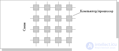
Fig.26.1. The connection scheme of processors in the form of a flat grid
With this type of connection, the maximum distance between processors will be equal to 6 (the number of connections between processors separating the closest processor from the farthest). The theory also shows that if the system has a maximum distance between processors of more than 4, then such a system cannot work effectively. Therefore, when connecting 16 processors to each other, a flat circuit is impractical. To obtain a more compact configuration, it is necessary to solve the problem of finding a shape with a maximum volume with a minimum surface area. In three-dimensional space, the ball has this property. But since we need to build a nodal system, instead of a ball, we have to use a cube (if the number of processors is 8, Fig.2.2.2) or a hypercube , if the number of processors is greater than 8. The dimension of the hypercube will be determined depending on the number of processors to be connected. So, to connect 16 processors you will need a four-dimensional hypercube . To build it, you should take the usual three-dimensional cube, move it in the right direction and, connecting the vertices, get a hypercube of dimension 4 (Fig. 26.3).
The hypercube architecture is second in efficiency, but the most obvious. Other topologies of communication networks are also used : a three-dimensional torus, a "ring" (Fig. 26.4), a "star" and others.
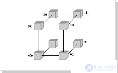
Fig.26.2. Communication topology, 3-dimensional hypercube
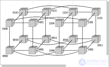
Fig.26.3. Communication topology, 4-dimensional hypercube
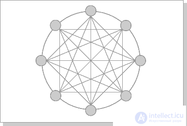
Fig.26.4. Chordal Ring Chordal Ring Architecture
The most effective is the architecture with the topology of a "thick tree" (fat-tree). The fat-tree architecture (hypertree) was proposed by Leiserson (Charles E. Leiserson) in 1985. The processors are localized in the leaves of the tree, while the internal nodes of the tree are arranged in an internal network (Fig. 26.5, 26.6). Subtrees can communicate with each other without affecting higher levels of the network.
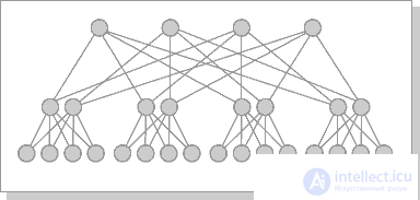
Fig.26.5. Cluster architecture "Fat-tree"

Fig.26.6. Fat-tree cluster architecture (top view of the previous scheme)
Communication environments of computing systems (VS) consist of adapters of computing modules (VM) and switches providing connections between them. Both simple switches , and compound, composable from a set of simple ones are used. Simple switches can connect only a small number of VMs due to physical limitations, but at the same time they provide minimal latency when establishing a connection. Composite switches, usually built from simple, multi-stage schemes using point-to-point lines, overcome the limitation on a small number of connections, but they also increase delays.
Types of simple switches :
- with time division ;
- with spatial separation .
Advantages: easy control and high speed.
Disadvantages: a small number of inputs and outputs.
Simple timed switches are also called busses or bus structures. All devices are connected to a common information highway used to transfer information between them (Fig. 18.11).
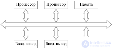
Fig.26.7. General scheme of the bus structure
Usually, the bus is a passive element; transmissions are controlled by transmitting and receiving devices.
The transfer process is as follows. The transmitter first accesses the bus , then tries to establish contact with the destination device and determine its ability to receive data. The receiving device recognizes its address on the bus and responds to the request of the sender. The transmitting device then reports what actions the receiving device should take during the interaction. After that, data transfer occurs.
Since the bus is a shared resource for which access devices connected to it compete, methods are needed to control the provision of device access to the bus . It is possible to use a central device to control access to the bus ; however, this reduces the scalability and flexibility of the system.
To resolve conflicts that arise when simultaneously requesting devices to access the bus , various techniques are used, in particular:
Inside the bus chips are used to combine the functional blocks of microprocessors, memory chips, microcontrollers. Tires are used to combine devices on printed circuit boards and circuit boards in blocks. Tires are also used in mezzanine technology, where one or more bus connectors are installed on a large board to install smaller boards, so-called mezzanines.
Tires that unite the devices that make up the computing system are a critical resource, the failure of which can lead to the failure of the entire system. Tires also have a number of fundamental limitations. The scalability of bus structures is limited by the time spent on arbitration and the number of devices connected to the bus. In this case, the more connected devices, the more time is spent on arbitration. The arbitration time limits the bus bandwidth. In addition, at any given time a bus is used to transmit only one device, which becomes a bottleneck as the number of connected devices increases. bus bandwidth is limited by its width - the number of conductors used for data transmission - and the clock frequency of its work. These values have physical limitations.
Simple switches with spatial separation allow you to simultaneously connect any input to any one output (ordinary) or several outputs (non-ordinary). Such switches are a set of multiplexers, the number of which corresponds to the number of outputs of the switch, with each switch input must be connected to all multiplexers. The structure of these switches is shown in Figure 26.8.
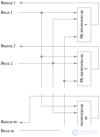
Fig.26.8. Simple Split Switch
Advantages:
Disadvantages:
Simple switches have limitations on the number of inputs and outputs, and may also require a large amount of equipment as this number increases (in the case of spatial switches). Therefore, to build switches with a large number of inputs and outputs, a set of simple switches combined with the help of point-to-point lines is used.
Composite switches have a delay proportional to the number of simple switches through which the signal passes from the input to the output, i.e. number of cascades. However, the amount of hardware on a composite switch is less than simple with the same number of inputs and outputs.
Most often, composite switches are built from rectangular 2 x 2 switches with two inputs and outputs. They have two states: direct transmission of inputs to the corresponding outputs and cross-transmission. The 2 x 2 switch consists of the actual data switching unit and the control unit. The control unit, depending on the incoming control signals to it, determines which type of connection should be made in the switching unit — direct or crossover. Moreover, if both inputs want to connect to one output, the switch resolves the conflict and connects only one input to this output, and the connection request from the second is blocked or rejected.
The Klose switch can be built as an alternative for a rectangular switch with (mxd) inputs and (mxd) outputs. It is formed from three cascades of switches: m switches (dxd) in the input stage, m switches (dxd) in the output and d intermediate switches (mxm) (Fig. 26.9).
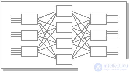
Fig.26.9. Switch Kloza 3x4
Connections inside the switch are arranged as follows:
This type of composite switch allows you to connect any input to any output; however, when connections are established, adding a new connection may require breaking and re-establishing all connections.
Banyan network
Switches of this type are built on the basis of rectangular switches in such a way that there is only one way from each input to each output.
The most important type of banyan network is the delta network. It is formed from rectangular switches (axb) and is an n-cascade switch with an inputs and bn outputs. Component switches are connected so that to connect any input and output a single path is formed which is the same for all pairs of inputs and outputs of length.
In distributed computing systems, resources are divided between tasks, each of which is executed on its own subset of processors. In this connection, the notion of processor proximity arises, which is important for actively interacting processors. Usually, the proximity of the processors is expressed in different cascade connections, different distances between them.
One of the options for creating composite switches is to combine rectangular switches (v + 1 x v + 1), v> 1 in such a way that one input and one output of each component switch serve as an input and output of the composite switch . A processor and memory are connected to each internal switch, forming a computing module with v-channels to connect to other computing modules. The free v-inputs and v-outputs of each computational module are connected by "point-to-point" lines with the inputs and outputs of other switches, forming a graph of intermodular connections .
The most effective graph of intermodular communications in terms of organizing the exchange of data between computational modules is a complete graph. In this case, there is a direct connection between each pair of computational modules. In this case, simultaneous connections between arbitrary computing modules are possible.
However, it is usually impossible to create a complete graph of intermodular links for several reasons. Data exchange has to be made through a chain of transit modules. Because of this, delays increase, and the possibility of establishing simultaneous connections is limited. Thus, an effective graph of intermodular links should minimize the time of intermodular exchanges and maximize the number of simultaneously activated compounds. In addition, the choice of inter-module communication graph is influenced by the consideration of failures and restoration of computational modules and communication lines.
Count intermodular communications MVS-100
Graph intermodule connections Convex Exemplar SPP1000
В качестве примера реального графа межмодульных связей рассмотрим структуру системы Convex Exemplar SPP1000. В основе каждого составного блока системы лежит прямоугольный коммутатор (5 х 5), до 16 подобных блоков объединяются каналами "точка-точка" в кольцо ( одномерный тор ), состоящее из четырех независимых подканалов (рис.26.10).
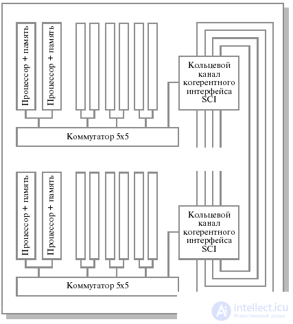
Рис.26.10. Граф межмодульных связей Convex Exemplar SPP1000
Внутри каждого блока четыре входа и выхода прямоугольного коммутатора (5 х 5) используются для взаимодействия устройств внутри блока (при этом в каждом блоке располагается по два процессора), пятые вход и выход используются для объединения блоков в кольцо. При этом каждый из четырех кольцевых каналов рассматривается как независимый ресурс, и система сохраняет работоспособность до тех пор, пока существует хотя бы один функционирующий кольцевой канал.
Система МВС-100 предлагает блочный подход к построению архитектуры параллельной вычислительной системы. Структурный модуль системы состоит из 16 вычислительных узлов, образующих матрицу 4х4 (рис.26.11). Угловые узлы соединяются попарно по диагонали, таким образом, максимальная длина пути между любой парой элементов равна трем. В исходной же матрице 4 х 4 эта длина равна шести. Каждый блок имеет 12 выходов, что позволяет объединять их в более сложные структуры.

Рис.26.11. Структурный модуль МВС-100
Для МВС-100 базовый вычислительный блок содержит 32 узла. Такой блок строится из двух структурных модулей в соответствии со схемой, приведенной на рис.26.12. В этом случае максимальная длина пути между любой парой вычислительных узлов равна пяти. При этом остается 16 свободных связей, что позволяет продолжить объединение. При объединении двух базовых блоков по схеме, приведенной на рис.26.12 (64 вычислительных узла) максимальная длина пути составит 6, как и в гиперкубе, а количество свободных связей будет равно 16.

Рис.26.12. Варианты объединения структурных модулей МВС-100
Архитектура системы МВС-1000 аналогична архитектуре МВС-100 . Основой системы является масштабируемый массив процессорных узлов. Каждый узел содержит вычислительный микропроцессор Alpha 21164 с производительностью 2 GFLOPS при тактовой частоте 500 MHz и оперативную память объемом 128 MB, с возможностью расширения. Процессорные узлы взаимодействуют через коммуникационные процессоры TMS320C44 производства Texas Instruments, имеющие по 4 внешних канала (линка) с общей пропускной способностью 80 Мбайт/с (20 Мбайт/с каждый). Также разрабатывается вариант системы с использованием коммуникационных процессоров SHARC (ADSP 21060) компании Analog Devices, имеющих по 6 каналов с общей пропускной способностью до 240 Мбайт/с (40 Мбайт/с каждый).
Процессорные узлы связаны между собой по оригинальной схеме, сходной с топологией двухмерного тора (для 4-линковых узлов). Аналогично МВС-100 , структурный модуль МВС-1000 состоит из 16 вычислительных модулей, образующих матрицу 4 x 4, в которой четыре угловых элемента соединяются через транспьютерные линки по диагонали попарно. Оставшиеся 12 линков предназначаются для подсоединения внешних устройств (4 линка угловых ВМ) и соединений с подобными ВМ.
Конструктивным образованием МВС-1000 является базовый вычислительный блок, содержащий 32 вычислительных модуля. Максимальная длина пути между любыми из 32 вычислительных модулей равна пяти, при этом число свободных линков после комплектации блока составляет 16, что позволяет продолжить процедуру объединения. Возможная схема объединения четырех базовых блоков в 128-процессорную систему приведена на рис.26.13.
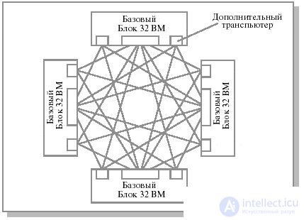
Рис.26.13. Структура 128-процессорной системы МВС-1000, 4 базовых блока
1. Кластерная архитектура.
2. Архитектура связи в кластерных системах.
3. Типы простых коммутаторов для многопроцессорных вычислительных систем.
4. Составные коммутаторы для многопроцессорных вычислительных систем.
5. Коммутатор Клоза.
6. Баньян-сети.
7. Граф межмодульных связей Convex Exemplar SPP1000.
8. Structural module MVS-100.
9. Options for combining structural modules MVS-100.
10. Structure of the 128-processor system MVS-1000, 4 basic blocks.

Comments
To leave a comment
Computer circuitry and computer architecture
Terms: Computer circuitry and computer architecture