Lecture
Depending on the target destination and the computer processor used, they differ significantly in their computational capabilities, size, and construction cost. Despite the fact that the principles of operation of the simplest microcomputers and mainframes are in general the same, the real structures and algorithms of functioning of even small modern universal computers (such as a personal computer) are very cumbersome and difficult for the initial understanding. In connection with these, a hypothetical machine with the features of many simple microcomputers is considered.
By definition, a microcomputer is a complete computing system built on the basis of a microprocessor and placed in one LSI (single-chip microcomputer) or several LSIs installed on one board (single microcomputer). Moreover, a complete computing system should be understood as any device for processing digital information, including a processor, memory and information input / output subsystem, regardless of its purpose, design, and programming methods.
As already noted, modern microcomputers mainly have a trunk-modular structure. Its basis, in the simplest case, is the only common highway to which, in the required nomenclature and quantity, all computer devices, made in the form of functionally complete units, are connected. In this case, all computer devices exchange information with each other only through the trunk, using similar sets of signals and exchange protocols.
Consider the minimum set of devices that is needed to create the simplest hypothetical microcomputer (Fig. 18.1).
A processor module that includes the MP itself, a clock pulse generator (GTI) and auxiliary control devices (VSUU) external to the MP.
· Modules of permanent and random access memory - ROM (ROM) and RAM (RAM), respectively.
· An information input / output (I / O) module containing transceiver devices (PUF) for communication with various peripheral devices (PU), which can also be called the intermediate interface adapter module.
· Power Supply (PSU).
· In general, it is possible to have a service keyboard module and a display built on seven-segment indicators or LEDs.
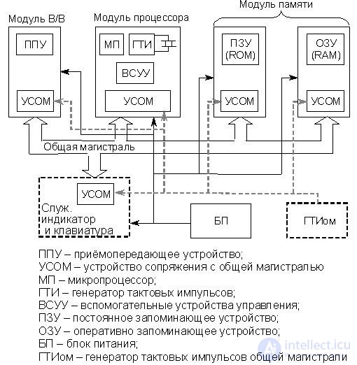
Fig.18.1. The generalized structure of the simplest microcomputer
All modules of microcomputers have interface devices with a common highway (USOM). They perform a number of important functions for the implementation of information exchange operations between microcomputer devices, which are discussed below. It should be emphasized that for different modules of microcomputers the structure of these devices and the functions they perform can be significantly different .
One of the simplest functions of USOM is to increase the load capacity of the microcomputer modules and their individual devices, since most of the logic circuits on which they are built cannot provide the signal power necessary for transmitting the OM.
In addition, the output (input) stages of the USOM blocks present in each module of the microcomputer have three steady states:
H - high level (logical 1);
L - low level (logical 0);
Z is the bus disconnect state.
In state Z, the output (input) resistance of the MSOM is large (determined only by leakage currents of pn junctions) and the corresponding microcomputer module can be considered disconnected from the main in general or from its individual lines.
Previously it was assumed that all devices of the micro-computer are synchronized from one clock generator located in the processor module and indicated in fig. 18.1 as a GTI. However, as shown in fig. 18.1, USOM can (but not necessarily) be synchronized from a separate clock generator, designated as GTI. The “ohm” index means that the clock generator synchronizes the exchange operations by the OM. It is also possible to synchronize computer devices and USOM units from one GTI. In some cases, as will be shown below, the synchronization of the USOM blocks of various microcomputer modules during the OM exchange is not required at all.
In the previous sections, the basic principles of operation of an elementary processor, the interaction of its main parts of the ALU and SU, as well as the principles of microprogram control of the operation of the processor, have already been considered. The basic principles of constructing memory devices, microcomputer command systems and program interruption systems are also considered.
Now consider the possible variants of microcomputer structures, which are largely determined by the structure of the OM and the algorithms for transmitting signals through it between different blocks, and then we proceed to consider the MP itself and the principles of functioning of the simplest microcomputer.
Modern processors are structurally performed either as a single LSI (VLSI), or as several LSIs installed on the processor module board in close proximity to each other. In addition, a number of auxiliary devices are usually placed on the processor module board, combined on the circuit (Fig. 14.1) into the VSUU block. Such devices can be a system controller, an interrupt controller, a direct access controller, timers, etc. The processor module board is installed on a common trunk. This connection can be physically realized as a connector or sealed contacts. In some cases, BIS MP is installed on the trunk itself.
When an MP module interacts with memory modules, information reading or writing operations are performed, and when interacting with a PU, information input / output operations are performed. At the same time, besides the actual data and addresses of memory cells or PU registers, it is necessary to transmit a large number of service control signals along the trunk. In view of this, the general highway is divided into three (in general) independent tires:
- address bus (ША);
- data bus (SM);
- control bus (SHU).
It is technically easier to use unidirectional tires, but then their number should increase, i.e. two tires each for operation "Read" (Input) and "Write" (Output). This leads to a significant increase in the number of contacts of the connector module MP or directly the very BIS MP, as well as the number of conductors OM. Meanwhile, any increase in the number of OM conductors always leads to an increase in the cost of a computer, and in some cases it is generally impossible due to technical limitations.
The most obvious way to reduce the number of LSI outputs and OM conductors is to combine unidirectional buses into one bidirectional, controlled by appropriate signals — read / read (READ / WRITE) for memory modules and input / output (INPUT / OUTPUT) for the PUF module. Below are 5 options for OM structures with only bi-directional tires.
· Separate tires (ris.18.2, a)
The use of separate bi-directional buses simplifies the exchange of the processor with the memory modules and the foam and gives it a fundamental opportunity to drive it in overlapping time intervals. At the same time, the address spaces of memory cells and FPU registers may overlap.
The main disadvantage of this structure is the large number of conductors of the common line and the contacts of the MP module.
· Insulated tires (ris.18.2, b)
The similarity of the exchange processes processor - memory and processor - registers PUF allows you to use in both cases the same conductors ША and ШД.
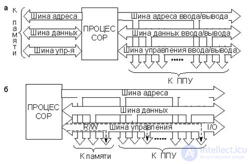
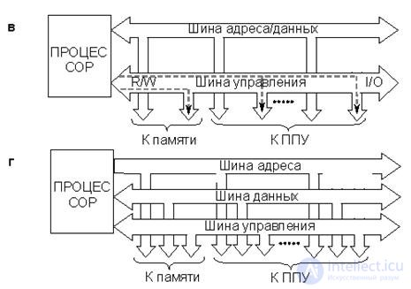

Fig.18.2. Micro-computer structures:
a - with separate tires, b - with insulated tires,
c - with isolated tires and bus multiplexing
addresses and data, d - with shared tires, d - with shared tires
and multiplexing address and data buses
This leads to an insulated tire structure. Address spaces of memory cells and PU registers, as with the previous structure, may overlap, i.e. they are isolated. In order to occupy the bus for the exchange with memory, the processor issues the signals READ / WRITE, and for the exchange with the PU - INPUT / OUTPUT.
Compared to the previous structure, the number of OM conductors (as well as the MP module) has decreased, but the fundamental possibility of parallel exchange with memory and PU has disappeared.
· Isolated busses and multiplexing of linear and external drives (Fig. 18.2, c)
In this case, the SHA and SM are combined. As a result, the transfer of addresses and data takes place at different times. Address spaces of memory cells and registers PUF isolated.
Compared with the previous structures, the number of common conductors and outputs of the MP module has decreased, but addresses and data can be transmitted only at non-overlapping points in time. This makes it difficult to pipe the process of executing commands and lengthens the processor-memory exchange cycle.
· General tires (fig. 18.2, d)
In this case, input / output commands (INPUT / OUTPUT) are generally excluded, which simplifies the structure of the MP module and the common trunk, although the number of conductors roughly corresponds to the structure with insulated buses. The memory cells and the FPU registers are in the common address space, and the same commands are used to access them.
In some cases this is an advantage, however, in the event of certain disruptions in the operation of the control center and their incorrect processing by the operating system, the computation process may “hang”.
· Shared buses and multiplexing of B & W (Fig. 18.2, e)
The disadvantages and advantages of this structure compared to the previous one ("common tires") are similar to those described above for the structure shown in Fig. 18.2, c.
Modern MPs, almost all, have input / output commands, i.e. make it possible to organize a structure with insulated tires. At the same time, all of them allow access to the PUU registers as memory cells, i.e. allow you to implement a structure with shared tires.
It should be noted that the structure of the bus "common tires" is very common in real devices. The concepts of "common highway (OM)" and "common bus (OSH)" are often used interchangeably in the literature, although according to the above classification, OSH is a particular case of the OM structure. Below, when presenting the material, the concepts of OR and OM will also be used as synonyms, unless otherwise indicated.
The considered OM structures largely determine the internal structure of a specific micro-computer. However, the structure of a micro-computer is also determined by a variety of issues related to the form of presenting information and how it is transmitted within the micro-computer, the interaction algorithms of individual modules.
For a comprehensive description of the structure of micro-computers use a very voluminous concept of " system interface ", which includes all the issues noted above.
A system interface is a set of circuits connecting a processor with memory and a PUF, algorithms for transmitting signals along these circuits, their electrical and temporal parameters, the type of connecting elements, design solutions, etc. (i.e., it is a set of hardware and software) .
Thus, OM is an important, but not the only component of the system interface that determines the structure of the micro-computer as a whole.
It should be noted that the term “system interface” is rarely used in literature when describing the structure of a computer. Shorter terms “bus” or “trunk” are commonly used.
There are many types of system interfaces developed for computers of various purposes. The number of standard system interfaces only amounts to dozens. A complete description of the system interface even of a single, specific computer is far beyond the scope of this course. Meanwhile, it is necessary to at least briefly dwell on another important component of the system interface - signaling algorithms for OM. More precisely, on the basic principles of the construction of these algorithms, since they also strongly influence the internal structure and general characteristics of a micro-computer. To do this, you must first introduce the concept of " tire cycle ".
As already noted, in the computer of a trunk-modular architecture, the presence of a single resource (trunk) makes it possible to exchange between devices only at non-overlapping points in time. This means that at each moment of time there is only one communication channel between two devices, which can be conventionally called "transmitter" and "receiver". There are various procedures for the exchange of OM. These are writing to the PD, reading from the PD, writing to the PU registers, reading from the PU registers, direct access to the memory, as well as various modifications of the indicated operations. The specific protocol that is exchanged between two computer devices always corresponds to the type of procedure being performed. When performing exchange operations, the ADM transmitter exposes the information to be transmitted on the trunk line. The receiver's COM, having received the appropriate control signals, must read it. Between the moment of installation of data on the lines of the line and their reading, a certain time interval arises, the value of which in general can vary. This is primarily due to the peculiarities of the interaction algorithm of a specific transmitter and receiver, as well as the fact that, in addition to transmitting the actual data, a number of service control signals are formed that are necessary to implement the exchange protocol, and their number and nomenclature may be different. The operations of the transmitter and receiver USOM units on the implementation of the exchange procedure can, but not necessarily, be synchronized by pulse sequences from the GTI or GTI (hereinafter referred to as “sync pulses”). Synchronization of exchange operations, if present, can be carried out both by fronts and by the levels of the sync pulses of the highway. When executing various exchange procedures between microcomputer devices, the number and nomenclature of service operations, and, consequently, the time intervals between the data establishing operations on the OM lines and their reading, can differ significantly. Moreover, the duration of exchange operations are different in a micro-computer using various types of system interfaces.
A bus (trunk) cycle is a set of service operations of the transmitter and receiver USOM units necessary for the implementation of a specific OM exchange procedure between two computer devices.
For a specific OM, there are various bus cycles that have the appropriate names for the types of exchange procedures implemented. These are the bus cycle of reading the register of the PPU (port), the bus cycle of reading the memory cell, the bus cycle of writing into the memory cell, etc.
The cycle time of a bus (trunk) is the time interval required for the implementation of a specific one-time OM exchange procedure between two computer devices. In the presence of synchronization of exchange operations, this interval can be measured by the number of necessary sync pulses of the highway (the number of bus cycles).
As already noted, the specific number, nomenclature and sequence of service operations (cycle structure), as well as their duration for different exchange procedures may vary significantly. Meanwhile, the basic principles of building protocols for various exchange procedures for a particular OM are the same . In general, there are 4 main types of exchange protocols (usually referred to as “type of cycles”), each of which determines the type of OM used in a particular computer and the features of its internal structure:
synchronous cycle (synchronous lines);
asynchronous loop (asynchronous trunks);
closed loop (closed line);
open loop (open line).
Consider these options for highways in more detail, given the fact that this classification describes the principles of the functioning of OM in various aspects. The first two points take into account the presence of synchronization when performing exchange operations. The last two are informational feedbacks between the transmitter and the receiver. This means that both synchronous and asynchronous trunks can be either closed or open .
· Synchronous trunks
A distinctive feature of highways of this type is the existence of a strict binding of all operations on the implementation of the exchange cycle to the fronts or levels of the main clock pulses.
The main advantage of synchronous trunks is that they have simpler logic control devices USOM and provide the highest bandwidth during the exchange. The main disadvantage of synchronous trunks is that they require integrated synchronization of USOM units, additional equipment and software, as well as approximately the same speed of all devices on the trunk.
· Asynchronous trunks
A distinctive feature of highways of this type is the absence of any synchronization of operations for the implementation of the exchange cycle, i.e.GTI om missing.
The main advantage of asynchronous highways is that they have increased flexibility and allow computer devices with different speeds to be connected in a single system. This property turns out to be very important when building open control systems, for example, automated process control systems. The main disadvantage of asynchronous trunks in limited bandwidth during data exchange. In addition, there is a need for additional lines for transmitting control signals, in particular a gating signal.
We will very briefly explain the meaning of the term “gating signal”, or simply “strobe”. When transmitting information on a parallel highway, there is always a problem with the moment of its reading. This problem is a consequence of some electrical asymmetry of the output stages of the transmitter MUST-controller and the OM lines caused by technological reasons. The indicated asymmetry leads to a variation in the time of the establishment of signals on different OM lines. On synchronous highways, this problem is solved by introducing a certain delay in the read operation relative to the corresponding synchronous pulse OM. On asynchronous highways, the time of reading information to the receiver must be indicated by a special signal - a gate,which comes from the transmitter to the receiver on a separate line with some fixed delay relative to the moment data is set on the OM lines.
· Closed highways
A distinctive feature of highways of this type is that there is a feedback between the transmitter and the receiver, the essence of which is as follows. The receiver, after reading the information from the OM lines, is obliged to notify the transmitter of the completion of the exchange cycle with any signal (receipt). For the transfer of receipts use either the line SD, or a dedicated line. With corrective codes, a receipt can inform the transmitter of the error that has occurred. There are various exchange algorithms for a closed line, but in any case, the transmitter does not start a new exchange cycle until a receipt is received. If there is no receipt for some timeout, an interrupt occurs and control is transferred to the operating system. This allows you to prevent errors in the system due to hardware failures and external interference.The latter is especially important for industrial equipment, i.e. systems of industrial control system.
The main advantage of closed highways is the increased reliability of the exchange for OM, which significantly increases the reliability of the computing system as a whole. The main disadvantage of closed highways is that they require additional equipment for the formation and transfer of receipts. In addition, the cycle time of the exchange increases slightly due to a timeout while waiting for a receipt.
· Open lines
A distinctive feature of highways of this type is that there is no feedback between the transmitter and the receiver. The transmitter, putting on the line OM the information to be transmitted, no longer “cares” about whether it is read by the receiver or not. It is assumed that information is necessarily read by the receiver and initialization of a new exchange cycle is possible.
The main advantage of open trunks is the simplicity of OM hardware and software, and consequently, lower cost. In addition, they have an increased exchange performance. The main drawback of open trunks is the increased likelihood of errors in the system due to hardware failures and external interference. This significantly limits the scope of open trunk applications.
Taking into account the above, it should be noted that the microcomputer considered below on the KR580VM80 processor is built on the simplest variant of the synchronous open line. Synchronization of all devices and exchange operations on the highway is carried out from one GTI.
A lot of PUs are usually connected to the microcomputer processor. These are keyboards, indicators, printers, drives, various sensors and actuators of control systems, etc. PU is characterized by a different speed, a different set of control signals, different electrical parameters, i.e. their internal interface (PU interface) is usually not compatible with the microcomputer system interface. To interface a microcomputer with a PU, it is necessary to use an intermediate interface supported on both sides by special adapters.(PUF), i.e. An intermediate interface for serial or parallel data transfer is introduced between the system interface of the microcomputer and the internal interface of the PU (Fig. 18.3). In principle, each PU may have its own intermediate interface. However, to simplify and unify the interface equipment, it is advisable to use a single standard intermediate interface . Using the same standard intermediate interface for serial or parallel data transfer to the microcomputer, you can connect different PUs.
Разнообразие ПУ и, прежде всего, их различное быстродействие (например, клавиатура и НМД) не позволяют в реальных микроЭВМ использовать только один тип промежуточного стандартного интерфейса. Между тем каждый из используемых в реальных микроЭВМ стандартных промежуточных интерфейсов позволяет подключать достаточно большие группы ПУ.
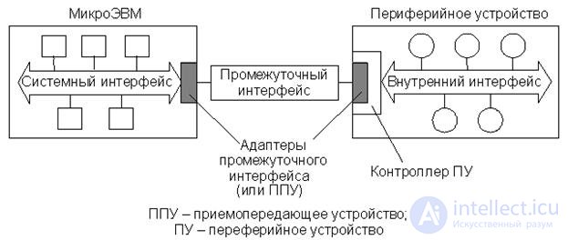
Рис.18.3. Включение промежуточного стандартного интерфейса
Существует большое количество стандартных промежуточных интерфейсов, адаптеры которых серийно выпускаются в виде БИС или встроены в БИС МП. В качестве примера можно указать два типа интерфейсов, которые можно назвать классическими – это последовательный интерфейс RS-232C и параллельный интерфейс CENTRONICS. Так, в первом отечественном микропроцессорном комплекте КР580 (прототипом является микропроцессорный комплект фирмы Intel I8080) присутствуют два типа программируемых ППУ – КР580ВВ51 (прототип I8251) и КР580ВВ55 (прототип I8255), являющиеся соответственно адаптерами последовательного и параллельного интерфейсов. Аналогичные ППУ присутствуют и в современных микропроцессорных комплектах. Например, ППУ UPD71051C и UPD71055 фирмы NEC или микросхемы серий 8211 и 8250/1645/16550 и их модификации фирмы Intel.
Наличие стандартного промежуточного интерфейса создает удобство в подключении различных ПУ к микроЭВМ. Однако этого недостаточно для ведения операций обмена с конкретным ПУ. Для каждого ПУ необходима специальная программа, которая, используя стандартный промежуточный интерфейс, будет вести обмен с конкретным ПУ. Такие программы называют драйверами устройств . Обычно они входят в состав операционной системы.
Таким образом, в системах ввода/вывода современных микро-ЭВМ можно выделить, как минимум два уровня сопряжения ПУ с процессором и памятью. На первом уровне ППУ сопрягаются с процессором и памятью через системный интерфейс микро-ЭВМ, который комплексирует отдельные устройства микро-ЭВМ в единую вычислительную систему. На втором уровне сопряжения ППУ микро-ЭВМ посредством шин связи соединяются с аналогичными ППУ соответствующих ПУ, т.е. реализуется стандартный последовательный или параллельный промежуточный интерфейс.
Современные ПУ являются, как правило, сложными функциональными устройствами, для управления которыми одних драйверов устройств оказывается недостаточно. Драйверы могут оказаться недопустимо громоздкими и требовать больших вычислительных затрат со стороны центрального процессора. Кроме того, оперативность управления только через драйвер для быстродействующих ПУ может оказаться недостаточной. В связи с этим в состав сложных ПУ всегда входят специальные устройства управления, называемые контроллеры ПУ.
Следует отметить, что понятие "контроллер ПУ" охватывает очень широкий круг устройств. Контроллеры современных ПУ, таких как видеосистемы, жесткие диски и т.п., представляют собой сложнейшие устройства, имеющие собственные процессоры и память, т.е. являются специализированными микро-ЭВМ с соответствующим программным обеспечением. В то же время контроллером ПУ может быть и достаточно простое устройство, состоящее из нескольких логических схем. В ряде случаев контроллер ПУ может вообще отсутствовать. Тогда работой ПУ полностью управляет драйвер устройства, а сигналы, поступающие через промежуточный интерфейс, непосредственно воздействуют на узлы ПУ. Необходимо иметь в виду, что в функции контроллеров современных сложных ПУ входит не только организация операций обмена с ядром ЭВМ, но и управление функционированием ПУ в целом, например все действия, связанные с организацией системы физических записей на жестком диске.
При наличии контроллера, что характерно для большинства современных ПУ, управляющие сигналы и данные, переданные по промежуточному интерфейсу от микро-ЭВМ, первоначально поступают в контроллер ПУ и подвергаются соответствующей обработке. Это обстоятельство отражено на схеме включения промежуточного интерфейса (рис. 18.3), где адаптер промежуточного интерфейса является как бы частью контроллера ПУ. Передача данных и сигналов состояния от ПУ к микро-ЭВМ также происходит под управлением контроллера ПУ.
Подсистемы ввода/вывода больших ЭВМ имеют гораздо более сложную, многоуровневую иерархическую структуру интерфейсов, управляемую специализированными канальными процессорами. Подобные подсистемы обеспечивают обмен данными с множеством сложных устройств, таких как дисковые массивы, графические станции, серверы баз данных, другие ЭВМ, удаленные терминалы и т.п. Их описание выходит далеко за рамки настоящего раздела.
Вводом/выводом (ВВ) называют передачу данных между ядром ЭВМ, включающим в себя процессор и ОП, и периферийными устройствами (ПУ).
Система ВВ – это единственное средство общения ЭВМ с внешним миром. Ее возможности в серийных ЭВМ представляют собой один из важнейших параметров, определяющих выбор машины для конкретного применения.
Несмотря на разнообразие ПУ, в настоящее время разработано несколько стандартных способов их подключения к ЭВМ и программирования ВВ. Существует три режима ВВ:
· Программный ВВ (нефорсированный).
· ВВ по прерыванию (форсированный).
· Прямой доступ к памяти (ПДП).
Реализация ВВ в каждом из этих режимов отличается программно-аппаратными затратами и, самое важное, скоростью выполнения операций обмена и непроизводительными затратами времени процессора. Суть каждого из трех режимов состоит в следующем.
Программный ВВ . Инициирование и управление ВВ осуществляет процессор по командам прикладной программы. ПУ играют пассивную роль и только сигнализируют о своем состоянии, в частности о готовности к операциям ВВ.
ВВ по прерыванию . Операции ВВ инициирует ПУ, генерируя сигнал запроса прерывания, при этом процессор переключается на подпрограмму обслуживания данного ПУ, вызвавшего прерывание. В результате выполнения подпрограммы (обработчика) осуществляется обмен данными. Действия, выполняемые обработчиком, определяются пользователем, а непосредственно операциями ВВ управляет процессор.
Таким образом, как при программном ВВ, так и при ВВ по прерываниям операциями обмена управляет процессор, поэтому очень часто эти два варианта обмена не разделяют и рассматривают их как программный ВВ. В англоязычной литературе – Programmed Input/Output (PIO) . Однако в настоящем курсе эти варианты обмена рассматриваются отдельно.
Прямой доступ к памяти . Процессор в передаче данных не участвует. Он отключается от системной магистрали, а все операции обмена данными идут под управлением специального управляющего устройства – контроллера ПДП . Этот режим используется для быстродействующих ПУ, когда пропускной способности процессора недостаточно.
В каждой ЭВМ применяются особые способы ВВ, различные конфигурации схем и типы устройств. Однако для большинства ЭВМ можно выделить следующие общие принципы:
· Передача данных осуществляется по общей системной магистрали (что характерно для микроЭВМ) либо по специальной магистрали ВВ (что характерно для мини- и больших ЭВМ). Иногда отдельная быстродействующая магистраль ВВ выделяется только для обмена в режиме ПДП.
· Подключение ПУ к системному интерфейсу осуществляется с помощью промежуточного интерфейса, поддерживаемого со стороны микро-ЭВМ и ПУ соответствующими адаптерами.
· Операции ВВ инициируются только в случае готовности ПУ к обмену. При наличии нескольких ПУ и обмене в режиме прерывания или ПДП вводится система приоритетов, позволяющая избежать конфликтов. В соответствии с этой системой контроллер прерываний или ПДП среди ПУ, готовых к обмену, в первую очередь обслуживает ПУ с высшим приоритетом.
· Передача данных осуществляется двумя способами:
- отдельными битами, и тогда промежуточный интерфейс называется последовательным ;
- полными словами (например, целым байтом), и тогда промежуточный интерфейс называется параллельным .
· The information transmitted in the process of explosives is divided into:
- on the actual data (denoted by D);
- control data (denoted by U).
Control data from the processor are also called command words or orders. They initiate actions that are not directly related to the transfer of data (starting the device, disabling interrupts, setting modes, etc.).
Control data from the PU are called status words. They contain information about certain signs (about the readiness of the device to transfer data, about the presence of errors during the exchange, etc.). The state is usually represented in decoded form - one bit for each attribute.
Taking into account all the above, it is possible to depict the most common software model of the intermediate interface adapter (PUF) connecting the system micro-computer mainline and the internal mainline PU. Such a generalized software model PPU is presented in Fig. 18.4. Each of these registers must have an address that can be identified by an address decoder.

Fig.18.4. Generalized software model PPU
Naturally, a specific adapter model may differ from a generalized scheme, for example, the status and control register can be combined into one register, instead of two unidirectional ports use one bidirectional, control registers can be several. However, the logical functions of these four registers remain.
In accordance with the various structures of the system trunk discussed earlier, there are two possible ways of organizing explosive operations.
Isolated BB (corresponds to the structure with insulated tires)
Isolated explosives assumes the presence of special explosive teams In MP KR580 these are the IN and OUT commands. The address space of the PUF registers is isolated from the address space of memory cells, i.e. PUF registers and memory cells can have the same address. The IN and OUT commands are double-byte. The first byte is the CPC, and the second carries information about the number of the addressed PPU and the number of the register addressed in it. At the same time, MP KR580 provides for the possibility of exchanging data on IN, OUT commands only between a battery and addressable registers.
BB on the common tire (corresponds to the structure with the common tires)
In this case, the addressing to the FPU registers is carried out as to ordinary memory cells, i.e. memory cells and FPA registers have a single address space. You can use all the commands to access the memory cells. This is convenient, however, part of the memory address space is used to address the PU registers, which can cause difficulties if the program is large and many PU.
PU and micro-computer can exchange fairly large amounts of information that can not be placed only in the registers of the processor. In view of this, often explosive operations are data exchange operations between the OP and the PU. As already noted, in order to increase the flexibility of the entire computing system, micro-computers are provided with three modes of explosive operations.
In the program explosive mode, all actions related to the explosive operations are implemented by the commands of the application program, and two types of exchange are possible - synchronous and asynchronous, which can be used in various situations.
Synchronous explosive
Such explosives can be used to communicate with PUs that are “always ready”, for example, LED indicators, or for PUs in which the exact time of operations is known, for example, the maximum time required to print one character.
In the first case, teams of explosives are placed at arbitrary points in the program. In the second case, the program should be designed so that the exchange commands go at intervals not less than the execution time of one exchange operation (i.e., the maximum execution time of the operation in the control panel).
This is the simplest form of exchange, requiring a minimum of software and hardware costs (it is also called unconditional explosive). However, when working with slow PUs, it is usually not possible to optimally load the processor for the period between data transfers.
Asynchronous BB
In this case, the interval between the exchange operations is set by the PU itself. The processor receives periodically information about the readiness of the control panel to exchange operations, analyzing the contents of the PUU status register, therefore the exchange process consists of two phases:
- verification of readiness of PU for the exchange;
- implementation of direct operations of explosives.
In the majority of cases, the first phase of the exchange is implemented by cyclically calling the contents of the PUF status register into the battery, comparing it with a mask and analyzing the result, a cycle of waiting for the availability of the launcher occurs The implementation of the wait cycle takes time, sometimes quite significant. This is a significant disadvantage of this type of exchange, since in the waiting period the processor cannot perform useful work, i.e. actually idle.
1. The generalized structure of the simplest micro-computer.
2. The structure of a micro-computer with separate tires.
3. Micro-computer structure with insulated tires.
4. The structure of micro-computers with isolated buses and multiplexing address and data buses.
5. The structure of a micro-computer with common tires.
6. The structure of a micro-computer with common tires and multiplexing address and data buses.
7. Give the definition of the bus cycle time.
8. The main types of communication protocols for tires.
9. Enable intermediate standard interface.
10. The modes of input / output information in the computer.
11. The generalized program model of the receiving-transmitting device.

Comments
To leave a comment
Computer circuitry and computer architecture
Terms: Computer circuitry and computer architecture