Lecture
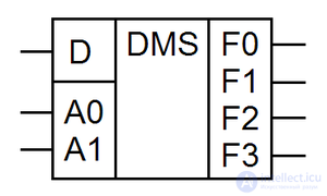
A demultiplexer is a logical device intended for switching a signal from one information input to one of the information outputs. Thus, the demultiplexer is functionally opposed to the multiplexer. In the diagrams, demultiplexers are denoted by DMX or DMS .
In the case of TTL logic, the AND switches are used for circuit switching. In CMOS chips widely used keys on field-effect transistors. Therefore, they lack the concept of a demultiplexer. Information inputs and output can be swapped, with the result that the multiplexer can serve as a demultiplexer.
If the ratio n = 2 m for binary demultiplexers or n = 3 m for ternary demultiplexers is valid between the number of outputs and the number of address inputs, then such a demultiplexer is called complete. If n <2 m for binary demultiplexers or n <3 m for ternary demultiplexers, then the demultiplexer is called incomplete. The functions of demultiplexers are similar to the functions of the decoders. The decoder can be considered as a demultiplexer, in which the information input maintains the voltage of the outputs in the active state, and the address inputs function as the inputs of the decoder. Therefore, in the designation of both decoders and demultiplexers in domestic chips use the same letters - ID.
Demultiplexers perform unary (single-input, single-operand) logic functions with n-ary output.
The device transmitting a signal from the information input to one of the outputs, and the number of this output is equal to the decimal equivalent of the binary code at the address inputs, is called a demultiplexer (DM) . As the DM, a decoder can be used, in which, instead of the OE signal, the information signal x is supplied . For example, if the inputs give the code a1a0 = 10 (BIN) = 2 (DEC), then the signal x appears at the output y2, and at the other outputs yi = 0. In Figure 16. given the symbol DM "1 in 4" and its mechanical counterpart.


Comments
To leave a comment
Computer circuitry and computer architecture
Terms: Computer circuitry and computer architecture