Lecture
Software-controlled explosives between OP and PU in many cases is far from being the most optimal, and sometimes impossible at all. There are several reasons for this. Consider very briefly the main ones.
· With software-controlled BB, the processor is "distracted" from the execution of the main program for solving the problem. Explosive operations are simple enough to efficiently load the logically complex high-speed processor hardware. As a result, when using software-controlled explosives, the performance of a computer as a whole decreases.
· When sending any data unit (byte, word), the processor executes enough commands to provide data buffering, format conversion, counting the number of transferred data units, generating memory addresses and control registers. As a result, the data transfer rate with software-controlled explosives (i.e., through a processor) may not be sufficient to work with high-speed PUs, for example, with hard disk drives, video systems, high-speed analog-digital and digital-analogue converters for various purposes, and .d
· Most modern complex PUs, such as video systems, network cards, hard drives, etc., exchange entire blocks of information with the OP. In this case, the above non-productive time costs of the processor become particularly significant.
· Exchange in the interrupt mode, despite all its advantages, also requires, in addition to the above-mentioned non-productive time, time to save the state vector of the current program on the stack and its subsequent recovery. In addition, interruption in most cases is possible only after the completion of the current command.
Despite the widespread use of software-controlled explosives, to speed up data exchange between the OP and PU and unload the processor from managing these operations, modern computers use a special exchange mode, called direct memory access mode or simply direct memory access (PDP). In English literature - Direct Memory Access (DMA ). Below, depending on the context of the presented material, both abbreviations will be used - RAP and DMA.
Direct memory access is a mode in which data is exchanged between PDs and PU registers without the participation of a central processor due to special electronic circuits external to it.
The introduction of the PDP mode (the implementation of the PDP channels) always complicates the hardware of the computer, but it allows to increase the speed of the OP-PU exchange operations, unloads the central processor from servicing the explosive operations, and improves the overall performance of the computer. If there is enough cache memory, the PDP mode in some cases allows parallel execution of exchange operations and processing of the current program by the processor, which also improves the overall performance of the computer. Moreover, the presence of a direct memory access mechanism allows maintaining the multiprocessing of the computing system. At the last moment you need to stop in more detail.
The fact is that the term PDP (as well as DMA), used in presenting the material of this section, generally does not accurately reflect the essence of the processes occurring in a computer. More precisely, direct access to the memory (to the OP) is only a special case of the organization of procedures for access to the system backbone from the side of many devices, including processors. The access to the system trunk is understood as the possibility of any device having the appropriate hardware and software (master device, intelligent device of the trunk) to occupy for some time the system highway and fully control it, producing all necessary control signals. In this case, communication can be carried out not only by OP-PU, but also by PU-PU. Meanwhile, the meaning of the concept of "memory" can be expanded and understood as a memory not only of the OP, but also the addressable registers of the PU. In this case, the use of the term PDP (as well as DMA) would be quite correct.
It should be borne in mind that the term "peripheral device (PU)" is used here quite conditionally. In the English-language literature, the master device of the highway initiating the exchange is called master. The device addressed by master is a slave, and it is called slave. Thus, it is more correct to talk about the implementation of master-slave (MS) connections, and not PU-PU or OP-PU. A master can only be an intelligent device that has trunk management tools (SUM), which, at a minimum, should be able to form and modify circulation addresses, control the size of the transmitted information block and generate trunk control signals. Meanwhile, depending on the current state of the computational process, the same intelligent device of the trunk can act both as a master and as a slave. Main line devices that do not have an SUM are always slave, i.e. slave
Naturally, the provision of a highway to a device (the seizure of a highway) can only take place on a priority basis. This procedure is called the highway arbitration , and the device that implements it is the highway arbiter . In some cases, the arbitrator can be built as a separate device located on the system backbone. In other cases, the bus arbitration is performed by the processor itself. The presence of the arbitration procedure allows you to place on the backbone of several intelligent devices, including processors. In accordance with the accepted discipline of service (arbitration), each of them will receive a system trunk and establish connections with both the PD and the registers of other devices on the highway. It should be noted, however, that the arbitration procedure always provides for means of preventing the exclusive seizure of a highway by a single device. Some of these funds can be concentrated in the arbitrator, the other part can be distributed between the main devices using the PDP mode.
Specific variants of procedures for access of the leading devices to the highway (organization of the RAP channels) in various computers are very diverse. Meanwhile, there are some general principles for their implementation. In general, for devices using DMA (DMA), there are two basic principles of access organization, in accordance with which there are two types of DMA systems (DMA).
Passive access or slave DMA . In this access method, all devices using the DMA mode are slaves and are serviced by one special DMA controller (DMA) located on the system trunk, i.e. one master device, - master. This access method allows you to implement only communication PU-OP. The DMA controller includes the line arbiter and the corresponding AML. In this case, the PUs play a passive role and exchange with the OP by the signals generated by the DMA controller, i.e. similar to how it happens when exchanging through a processor.
As noted above, the DMA controller serves several PUs, i.e. supports multiple DMA channels. Before the exchange, the controller must be initialized. To do this, it is necessary to load into its registers the starting address of the OP area with which the exchange is carried out, the size of the transmitted information block for each channel, the direction and mode of transfer, the arbitration discipline. In the general case, the initialization of the controller can be performed as necessary (repeatedly) during the processing of the current program. However, the installation of the discipline of arbitration in the absolute majority of cases is carried out once, when the computing system is started up to solve a specific problem.
Thus, the slave DMA does not require significant complication of the equipment of the devices of the highway, and consequently, an increase in their cost. Each device that uses this exchange mode should have only the signaling equipment of the request for the PDP (interrogator). At the same time, the DMA controller is a rather complicated and expensive device that can be considered an input / output coprocessor that relieves the central processor from routine exchange operations (that is, the PDP controller is a very simplified version of mainframe channel processors).
Historically, DMA slave systems appeared first. In particular, the PDP system of this type was used initially on the ISA backbone in IBM PC / XT computers. Numerous variants of the slave DMA systems are used in the universal and control computers of the most diverse architecture, purpose and performance.
Active access, or bus master DMA . With this access method, it is assumed that devices using the DMA mode have software and hardware capable of controlling the trunk (direct control of the trunk, or bus mastering ) and, therefore, implement any master-slave (MS) connections. Such trunk devices can act as master, so there is no single DMA controller. It remains only to the arbiter of the line, which, according to a certain discipline, makes the line available to one or another device. The arbitrator can be executed as a separate device placed on the trunk, or the processor can deal with arbitration of the highway. In modern IBM PC, trunk arbitration procedures are included in the chipset functions. If there are multiple processors, one of them may be appointed as arbiter.
It should be borne in mind that any modern intelligent device is controlled by a processor (processors) located on the system trunk and having its own expansion bus. Such a device is actually a specialized micro-computer, functioning according to a program, usually stored in its own ROM. This, in essence, is the only thing that differs from the "central processor (CPU)", which is also located on the system trunk and processes the current program commands stored in the RAM or system ROM. This approach allows us to consider the "CPU" as one of the intelligent devices of the highway, and the "CPU" can be several. Based on this, in computing systems using bus mastering, one can speak of a multitude of intelligent devices whose priorities for using the system backbone for the exchange (capture of the backbone) are determined only by the discipline of service loaded into the arbitrator during initialization, i.e. You can talk about multiprocessor computing systems.
Thus, bus master DMA requires significant complication of trunk devices (the presence of an AML, a more complex interrogator), and, therefore, an increase in their cost. However, it makes it possible to speed up the exchange processes, especially in multitasking mode, and implement multiprocessor versions of computing systems that have a trunk-modular architecture.
An example of devices with active DMA are ATA controllers (AT Attachment for Disk Drivers) located in modern IBM PCs on the PCI backbone, in particular the IDE controllers. Active DMA uses the SCSI (Small Computer System Interface) host bus adapter, which connects the bus to any internal backbone of the computer, as well as graphics system controllers and their means of connection, such as the Accelerated Graphic Port (AGP) port and a number of other devices. An example of devices that use only bus master DMA (bus mastering) are devices based on VME (Versa Module Eurocard) backbone computing systems.
It should be noted that in real computing systems, both versions of DMA systems are sometimes used simultaneously (for different devices of the backbone). In this case, the controller can support multiple DMA channels and work in a combined mode. For some devices of the trunk (slave), it can perform the functions of a DMA controller, and for other devices (master) it is only the arbiter of the trunk. It is this version of the functioning of the DMA system was implemented in IBM PC / AT.
Specific technical implementations of PDP systems have many options. They depend on the type of system bus, the architecture of the computer as a whole, the type of processor used, the purpose of the computer, the number of devices on the bus, etc. At the same time, they are complex combinations of a small number of basic structures of FPU systems. Below are two main basic structures - radial and chain.
Radial structure
Simplified versions of the generalized structures of radial-type PDP systems are presented in Fig. 20.1.
A characteristic feature of the radial structure is that each FPGA (in the particular case of PU) is connected to a separate input of the PDU controller (Fig. 20.1, a) or the arbitrator (Fig. 20.1, b). The difference between the two structures is that in the case of a slave DMA, a single LZPD line is enough to connect an DFMD, according to which the device issues a service request. In the bus master DMA system, at least three lines are needed to connect the device to the arbiter - LZPD, LPZ and LRPD, which can be called the arbitration bus (SHAR), which has its own entrance to the arbitrator. Each input (to the controller, to the arbiter) has a certain level of priority. The number of connected DFDs is determined by the number of inputs to the controller or arbiter.
When servicing devices using slave DMA (Fig. 20.1, a), the entire exchange is controlled by the RAP controller, the required components of which are the SUM block and the trunk arbiter. Trunk devices are passive and must contain only the interrogator.
When servicing devices using the bus master DMA (Fig. 20.1, b), the PDU controller, as such, is missing and only trunk arbitration is performed centrally. The trunk devices are active, so their requisite components are the interrogator and the SUM block (as already noted, "CPU" is considered in bus mastering systems as one of the DFID). After the acquisition, the trunk is controlled by the SUM unit of the specific device leading the exchange (master). As the arbiter of the line, either a specialized device or a PDP controller is used, in which the functions of the AML block are disabled. The LRDP lines present in the bus master DMA system are designed to transmit a RPD signal that allows the active device to capture the trunk. In addition, in the bus master DMA system there are necessarily LPS lines, the signals of which inform the arbitrator about the seizure of the highway by one or another device. The PZ signal always sets the master and keeps it on the line all the time while exchanging (controls the trunk), therefore the signal is always represented by the potential.
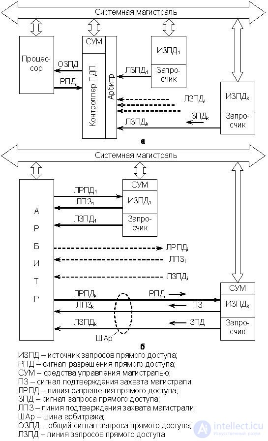
Fig.20.1. The radial structure of the system: a - Slave DMA, b - Bus Master
In systems of the radial structure, the PDU controller can operate, as noted above, in a combined mode, i.e. support both the slave DMA system and the bus master DMA system. Requests from the DATS in both DMA systems can be represented by both the potential level and its differential, since they are sent to the controller or arbiter on separate lines. However, the presentation of the request by the potential is more preferable, since the DMA system becomes more resistant to both interference and equipment failures. This significantly reduces the likelihood of missing a request from an IDPD.
The main advantage of the radial structure is that the equipment of the arbitrator of the highway is simplified, since each EPDD has its own LZPD. In addition, the EPRF hardware and slot design are somewhat simplified even in the case of bus master DMA, since all active devices of the trunk have a separate arbitration bus (ORB). All this reduces the cost of the radial system compared to the chain-based one, discussed below.
Chain structure
A simplified version of the generalized structure of the PDP chain type system is shown in Fig. 20.2.
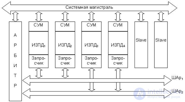
Fig.20.2. Generalized chain structure of the Bus Master DMA system
A characteristic feature of the chain-like structure is that the set of active trunk devices (OFD), the required components of which are the SUM block and the interrogator, are connected to one or more arbitration buses (RPA). In fig. 20.2 there are two balls. After the acquisition, the trunk is controlled by the SUM unit of the specific device leading the exchange (master). There is no PDP controller, and only trunk arbitration is performed centrally. In fig. 20.2 the arbitrator is depicted as a separate line device, although, as noted above, arbitration can be performed by the processor (one of the processors). Each CHA corresponds to one entrance to the arbiter and has its own priority level. Thus, the RDTs connected to different balls have different priority. Passive devices of the trunk (slave) to the ball are not connected. In addition, the priority of devices connected to one CHA is also determined by their position in the distribution circuit of the direct access enable signal (RPD).
Let us consider this point in more detail using the example of a single CHAR n bus master DMA system, the simplified structure of which is shown in
rice 20.3.
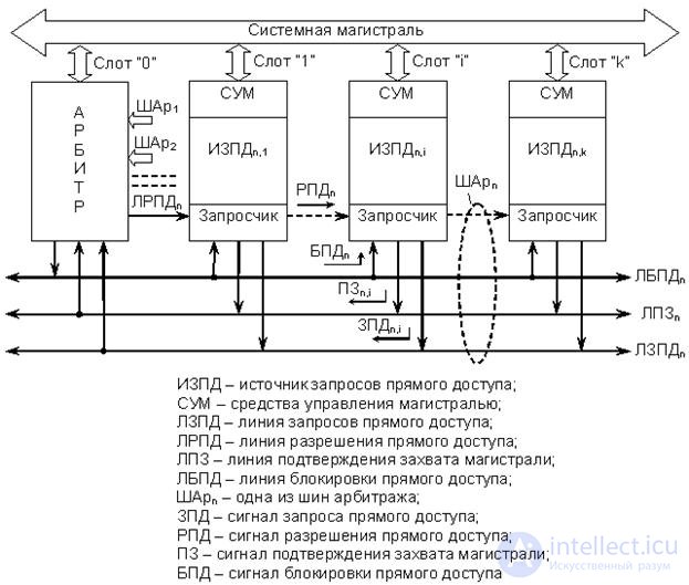
Fig.20.3. Arbitration bus structure ”n” of bus master DMA chain type system
It follows from the figure that the ORB (to simplify the notation here and below, the index "n" is omitted) in such a system contains at least four lines - LZPD, LRPD, LPZ and LDBD. Unlike the radial structure, the VFD lines are connected to the three ShA lines (LZPD, LPZ and LBPD) in parallel, therefore requests from the VFD (ZPD signals) are always represented by the potential level. The output stages of the hardware for the formation of requests in each of the FPGA are open-collector keys, combined according to the mounting scheme "or". This allows us to exclude the loss of requests simultaneously issued by different IDPDs to one LZPD.
The RPD signal is propagated sequentially through all devices until its distribution is blocked by the requestor of DFD i , who sent a direct access request (AP signal i ). Thus, the priority of the master of the highway is determined by its position in the propagation chain of the RPD signal. Let the referee be located in the slot with the number "0". Then the priority of devices located in subsequent slots will decrease with increasing slot number. In the absence of a device in the slot, it is necessary to take measures so that the propagation circuit of the RPD signal does not break. This is provided either by a special slot contact design, or by installing a jumper on the motherboard.
The signal of the LPZ line, as well as in the radial bus master DMA system, informs the arbitrator about the seizure of the highway by this or that device. This signal always sets the master and keeps it on the line all the time while exchanging (controls the trunk), so the signal is always represented by the potential.
Line LPBD - common to all the balls and is designed to transmit from the arbitrator signal blocking direct access (BPD), which prohibits bus mastering all intelligent devices trunk. This may be necessary, for example, when a request appears on a LZPD CHA line of higher priority (if there are several balls) or if the trunk is held by one device for an unacceptably long time.
It should be borne in mind that the chain structure systems practically only work in the bus master DMA mode, since the line arbiter can only identify the PDRD from which the request came, and determine its priority. When implementing the slave DMA mode, the DMA controller will need to identify a specific DFID on that line. The controller can perform such an operation only by sequentially polling the line devices, which will significantly increase the arbitration time and complicate the hardware of the devices. Meanwhile, the technical implementation of such systems is possible.
The main advantage of the chain structure is the almost unlimited number of RDCs connected to one arbiter input (one CHA) without slowing down. However, the complexity and amount of hardware support for the bus mastering system in each DFID increase, which leads to an increase in the cost of the system.
The use of any version of the RAP raises a number of problems associated with the use of a common highway by several devices. Even when using the simplest version of the DMA (slave DMA), which is discussed below, there is a problem of sharing the trunk with two devices - a processor and a DMA controller. To obtain the maximum rate of exchange, it is desirable that the PU, through the PDU controller, has a direct connection with the OP computer, i.e. would have a special highway, as is done in some cases. However, this solution significantly complicates and increases the cost of a computer, especially when several PUs are connected, therefore most of the simplest micro-computers use system bus for exchanging data in the FPU (organization of FPA channels) mode. This option is considered below. It is also assumedthat the cache memory is missing and the data (as well as commands) go to the processor directly from the RAM. The latter means that during the whole exchange period, i.e. while the controller is controlled by the master (s) master, the processor is forced to idle because it does not have access to the PD.
Despite the fact that such a method of organizing the exchange in the PDP mode is characteristic only for the simplest microcomputers, using his example, one can quite clearly illustrate the basic principles of direct control of the highway from the side of the master device. Studying the mechanism of functioning of bas mastering means of more complex computing systems always requires a sufficiently detailed consideration of the signals of a particular system bus, the processor used, the features of the architecture of the leading devices, etc.
The problem of sharing the system interface bus by the processor and the PDU controller generally has two main ways to solve it - PDU with loop capture and PDU with processor lock.
RAP with capture cycle
This method of PDP is designed to exchange short blocks of information in the form of a byte or word and has two options.
Option 1 .For the exchange, those intervals of the machine cycle of the processor are used, in which it does not exchange data with the memory or registers of the PU. In this embodiment, the controller PDP does not interfere with the processor. However, it is necessary to allocate such intervals to eliminate the temporary overlap of the exchange of the PDU controller and the processor. In some cases, the processors generate special signals that indicate the cycles in which the processor does not conduct exchange operations. In other cases, special circuits external to the processor are used, which identify such "free" time intervals.
The use of this variant of the PDP does not reduce the performance of the processor, but data transfer occurs only at random times. This lowers the overall rate of exchange. In addition, for some PUs, such an exchange mode is generally unacceptable.
Option 2 .For the time it takes to exchange one byte or a data word (which is several cycles), the processor is forcibly disconnected from the buses of the system trunk. This method of organizing a RAP with a loop capture is the most common.
When the PU is ready to exchange, it generates the signal of the PTA, which enters the PDP controller. He, in turn, produces a similar control signal (OZPD), which enters the processor. The OZPD signal is generated by the controller when the ZPD signal (signals) appears on any line (lines) of the LZPD and causes the processor to disconnect from the system trunk for several cycles. Having received this signal, the processor ends the exchange operations on the trunk. Then, without waiting for the completion of the current command (or machine cycle), it gives the PDP a RPD signal and disconnects from the system bus. At the same time, internal operations in the processor after the completion of the current command (or machine cycle) continue and can be combined in time with the operations of the RAP.
From this point in time, all the buses in the system trunk are controlled by the PDU controller. Using the system trunk, it performs the exchange between PU and OP in one byte or word, and then, removing the signal OZPD, returns control of the system highway to the processor. As soon as the PU is ready to exchange again, it generates an SZD signal, the PDP controller captures the trunk, and the exchange cycle repeats. In between the signals of the SPD, the processor continues to execute commands from the current program.
Thus, unlike the interrupt mode, which is entered only after the completion of the current command, the PDP mode is entered without waiting for it to complete. This is due to the fact that in the PDP mode, the internal registers of the processor are not used, their contents are not modified, and consequently, they do not require storing in the stack.
Naturally, the use of such a method of organizing the RAP slows down the execution of the program, but to a lesser extent than when exchanged in the interrupt mode. In addition, in contrast to option 1, the exchange occurs at those points in time at which it requires PU, which is especially important when the microcomputer operates in real time.
It should be noted that this version of the RAP is used only when the time intervals between the moments of readiness of the launcher for exchange are long enough and allow the processor to perform several operations.
PDP with processor lock
This mode differs from the RAP with "loop capture" in that the control of the system interface is transferred to the PDU controller not for the duration of the exchange of one byte or word, but for the entire duration of the data block exchange. In this case, all issues related to the synchronization of the PU and OP, are also solved by the PDU controller (in the "capture cycle" mode, the processor actually solved them). This mode of PDP is especially necessary in cases where the processor does not have time to execute at least one command between successive exchange operations in the PDP mode.
The PDP mode with processor locking in modern computers is basic, since modern PUs, such as hard and optical disks, video systems, printers, scanners, etc., always exchange information blocks of substantial volume. However, for their transmission, the PDU controller must hold the trunk for a sufficiently long time, during which the processor will stand idle. This will significantly reduce the performance of the considered simplest microcomputer as a whole.
Между тем, как уже отмечалось, процессоры большинства современных ЭВМ работают с ОП через кэш-память. При наличии кэш-памяти достаточного объема (особенно многоуровневой) процессор может продолжать некоторое время обработку команд текущей программы – до тех пор, пока необходимая информация присутствует в кэш и не требует обновления. Это время достаточно ограничено, поэтому арбитр должен следить за тем, чтобы время удержания магистрали контроллером ПДП не превышало некоторой, наперед заданной величины и простои процессора были сведены к минимуму.
Следует отметить, что реальные контроллеры ПДП, как правило, могут работать в различных режимах организации ПДП, зачастую комбинированных, поэтому рассмотренная выше классификация способов организации ПДП является весьма условной (особенно ПДП с блокировкой процессора и вариант 2 ПДП с захватом цикла).
Любой способ организации обмена в режиме slave DMA предполагает инициализацию контроллера со стороны процессора. Для этого, как уже отмечалось, перед началом обмена с ПУ в режиме ПДП процессор должен загрузить в регистры контроллера для каждого канала ПДП начальные адреса выделенных областей памяти и их размер в байтах или в словах в зависимости от того, какими единицами информации ведется обмен, направление и режим передачи. Кроме того, если конкретный контроллер это позволяет, программа инициализации должна установить дисциплину обслуживания каналов ПДП (арбитража), а также запрограммировать внутренний таймер, контролирующий время удержания магистрали.
All the above is true for the simplest exchange option - slave DMA, in which the PDP controller manages all exchange operations. When using the bus master DMA mode in both radial and chain structure systems, there is no PDP controller. It remains only to the arbiter line, which also requires initialization. Depending on the “intelligence” of the arbitrator, its initialization is carried out either manually using switches (jumpers) or programmatically. In the latter case, the initialization is carried out either from the built-in ROM, or one of the leading devices of the trunk when the computing system is started. The discipline of arbitration in this case remains unchanged throughout the operation of the computing system. However, if it is possible to change the discipline of the arbitration,Re-initialization of the arbitrator can be performed while the current program is being processed by the processor of one of the main devices of the line.
In general, the SUM of intelligent trunk devices, which can act as master, also require initialization, i.e. download addresses and exchange modes, the size of the transmitted blocks of information, etc. However, in many cases, the master leads the exchange, guided only by the needs of its own software, recorded in the local ROM.
Let us consider simplified exchange organization (highway capture) algorithms for both structures of the PDP systems — radial and chained.
In accordance with Fig. 20.1, and all requests from the IDPA are received by the arbitrator of the PDP controller mainline and are generally recorded there in some way. The sequence of operations to provide the highway to the controller of the RAP during the transfer of a data block is generally the following:
1. Перед началом обмена происходит инициализация контроллера ПДП со стороны процессора. Эта процедура описана выше и здесь не конкретизируется.
2. Процессор продолжает выполнять команды текущей программы до поступления запроса от какого-либо ИЗПД.
3. При возникновении готовности какого-либо из инициализированных ПУ его запросчик вырабатывает сигнал ЗПД, поступающий по соответствующей ЛЗПД в арбитр контроллера ПДП.
4. При поступлении запроса от любого ИЗПД (т.е. сигнала ЗПД по любой ЛЗПД) арбитр контроллера ПДП формирует сигнал ОЗПД, который транслируется в процессор. При этом в контроллере инициализируется процедура поиска запроса с максимальным приоритетом, если одновременно поступило несколько запросов. Эта процедура выполняется обычно аппаратным способом, например с помощью дейзи-цепочек или логических схем.
5. The processor finishes the exchange operations on the trunk, sends the RPD signal to the controller and disconnects from the buses of the system trunk. From this moment on, the system bus is controlled by the master controller. In addition, the controller starts an internal timer that monitors the hold time of the line.
6. The SUM controller's PDA block sets the exchange address and control signals that initiate the exchange. The result of this operation is the exchange between the OP and the most priority PU in one byte or word.
7. The SUM block of the PDP controller modifies the exchange address and the byte counter.
8. The AML block controls the size of the transmitted data block. The control can occur both by the number of transmitted bytes (words), and at the final address of the exchange area.
9. Блок СУМ контролирует время удержания магистрали контроллером ПДП по внутреннему таймеру.
10. Дальнейшие действия зависят от результатов операций в п. 8 и 9, а именно:
· Если обмен не закончен и время удержания магистрали не истекло, то происходит повторение операций, начиная с п. 6.
· Если блок информации передан полностью (обмен закончен), то контроллер ПДП снимает сигнал ОЗПД и освобождает системную магистраль.
· Если время удержания магистрали истекло (хотя обмен и не закончен), то контроллер ПДП освобождает магистраль и снимает сигнал ОЗПД.
11. Процессор продолжает выполнение текущей программы, либо, если запрос уже поступил, начинается процесс обслуживания канала ПДП с меньшим приоритетом (см. операции, начиная с п. 4).
It is possible that in the course of servicing one of the devices in the trunk, the arbiter of the PDP controller receives a request from a device with a higher priority. In this case, the controller PDP, without removing the signal OZPD, stops servicing the device with a lower priority and switches to servicing a higher priority device.
In accordance with Fig. 20.1, b all requests from the FPGA are received by the arbitrator of the highway (there is no PDP controller) and in the general case are recorded there in some way. It should be remembered that in the bus master DMA system, the “CPU” is considered as one of the main devices of a highway with its priority, i.e. as one of izpd. The sequence of operations to provide the highway to one of the masters (master) for transmitting a block of information is generally the following:
1. At the beginning of the operation of the computing system, the arbiter and, if necessary, the SUM of the main devices of the highway are initialized. This procedure is described above and is not specified here.
2. We believe that the computing system is functioning. The processors of the master devices execute commands of the corresponding programs and periodically seize the trunk to implement the MS exchange.
3. In the event of the readiness of any of the leading devices of the trunk, the interrogator generates an SPS signal, which arrives at the corresponding LZPD to the arbitrator.
4. When a request is received from any DFR (i.e., an FET signal on any LZPD), the arbiter of the line will analyze the signals of the LPS lines. The presence of a signal on any line means that the trunk is currently occupied by another device conducting the exchange. At the same time, the procedure for determining the priority of the incoming request (or requests, if there are several of them) is performed. Let the highest priority be the request from the FPIC i .
5. Further operations depend on the result of the analysis of the LPS lines (PZ signals), namely:
· In the absence of PZ signals on LPP lines (i.e., a free highway), the arbitrator places the RPD i signal on the RPRP i line of the highest priority EMR i device.
· If there is a PZ signal on any of the LTP lines (ie, a busy trunk), the arbitrator compares the priority of the device occupying the trunk with the priority of the highlighted request (ie, the priority of SpA i ).
- If the priority of the incoming request is lower , the arbiter waits for the end of the current exchange and removal of the PZ signal. After that, the arbitrator places the RPD i signal on the LRAP i line of the highest priority EPD i device.
- If the priority of the incoming request is higher , then the arbiter removes the RPD signal from the LRAP line of the device conducting the exchange, i.e. prohibits him from bus mastering. The device stops the exchange operations, frees up the trunk and removes the PZ signal. Only after this, the arbitrator places the RPD i signal on the LRAP i line of the highest priority EPD i device.
6. The arrival of the RPD signal enables the bus mastering device, i.e. seizure of the highway. From this point on, the system trunk is controlled by the SUM unit of the selected EDI device i (master), which also sets the PZ signal i . In addition, an internal timer is started in the arbitrator or in the DATT i , which controls the time the line is held.
7. The SUM block of the ADMS i (master) sets the exchange address and control signals that initiate the exchange. The result of this operation is the exchange of MS in one byte or word.
8. The active device SUM block modifies the address and byte counter.
9. The active device SUM block controls the size of the transmitted data block. The block size is usually controlled by the number of bytes (words) transmitted.
10. The time of holding the line by the device conducting the exchange is monitored. This control can be carried out both by the arbitrator and by the DATS device i by the built-in timer.
11. Further actions depend on the results of operations in clauses 9 and 10, and
exactly:
· If the exchange is not completed and the line retention time has not expired, then a repetition of operations begins, starting with paragraph 7.
· If the information block is transmitted completely (the exchange is completed), the master releases the system trunk and removes the signal PZ i .
· If the line holding time has expired (although the exchange is not completed), the master releases the trunk either by itself or after the arbitrator removes the RPD signal i .
12. The procedure for capturing the main line with a lower priority master (organization of the MS channel) begins if the request has already been sent to the arbitrator (see operations starting from point 4).
It should be noted that, in general, bus master DMA systems of a radial structure are possible, in which the arbiter acts as a slave device in relation to the CPU. In this case, before giving the trunk to an individual DATS, the arbitrator requests the CPU that uses the trunk exclusively, i.e. as in the case of slave DMA. However, this DMA option is not covered in this section.
In accordance with Fig. 20.2 many IDPD interrogators can be connected to each ORM (arbiter input). The signal of the RPD is distributed along the chain of IDDs connected to one LZPD (to one ball). The propagation of this signal is blocked by the IPDS that made the request. Let this be the DATS i , connected to WARNER n (see fig. 20.3). Having received the RPD signal, the SUM ISTP block n, i captures the trunk and starts to control it. Thus, the priority of devices connected to one LZPD is determined by the position of the DPRD in the RPD signal distribution chain. This eliminates the need to perform the search procedure with the highest priority among DFDs connected to the same LZPD.
If the IDE is multiple, which is usually the case in real bus master DMA systems of a chained structure, the arbitrator performs the search procedure for the excited LZPD with the maximum priority, which is similar to the search procedure for the request with the maximum priority in the radial structure system.
Based on the above, you can write a generalized sequence of basic operations to provide the highway to the master device (master) for transmitting a block of information:
1. At the beginning of the operation of the computing system, the arbiter and, if necessary, the SUM of the main devices of the highway are initialized. This procedure is described above and is not specified here.
2. We believe that the computing system is functioning. The processors of the master devices execute commands of the corresponding programs and periodically seize the trunk to implement the MS exchange.
3. In the event of the readiness of any of the leading devices of the trunk, the interrogator generates an SPS signal, which arrives at the corresponding LZPD to the arbitrator.
4. When a request is received from any DFR (i.e., an FAD signal on the LZPD of any ORB), the signal of the FAP lines is analyzed at the arbitrator of the line. The presence of a signal on any line means that the trunk is currently occupied by another device conducting the exchange. At the same time, the procedure for determining the priority of the BER, with which the request was received (or requests, if there were several of them) is performed. Let the highest priority was the request for the CHAR n .
5. Further operations depend on the result of the analysis of the LPS lines (PZ signals), namely:
· In the absence of PZ signals on LPP lines (i.e., a free highway), the arbitrator places the RPD n signal on the LRAP n line of the most priority BOM.
· If there is a PZ signal on any of the LPZ lines (ie, a busy trunk), the arbitrator compares the priority of the device occupying the trunk with the priority of the highlighted request (ie, the CHA priority n ):
- If the priority of the incoming request is lower , the arbiter waits for the end of the current exchange and removal of the PZ signal. After that, the arbitrator puts the RPD signal n on the LRAP line n of the highest priority Ball n .
- If the priority of the incoming request is higher , then the arbitrator sets the signal of the BPD on the LBDB CHA line, i.e. Disables active bus mastering devices. The device stops the exchange operations, frees up the trunk and removes the PZ signal. Only after this, the arbitrator places the RPD signal n on the LRAP line n of the highest priority ID n .
6. The arrival of the RPD signal n permits the devices to the BIR n bus mastering, i.e. seizure of the highway. The propagation of the RPD signal n is blocked by the IDP device n, i , put the request. From this point on, the system bus is controlled by the SUM unit of the selected EDI device n, i (master), which also sets the PZ signal n , i . In addition, an internal timer is started in the arbitrator or the VFD itself n, i , which controls the time the line is held.
7. The SUM block of the active device of the trunk (master) sets the exchange address and control signals that initiate the exchange. The result of this operation is the exchange of MS in one byte or word.
8. The active device SUM block modifies the address and byte counter.
9. The active device SUM block controls the size of the transmitted data block. The block size is usually controlled by the number of bytes (words) transmitted.
10. The time of holding the line by the device conducting the exchange is monitored. This control can be carried out both by the arbitrator, and by the IDT device n, i by the built-in timer.
11. Further actions depend on the results of operations in clauses 9 and 10, and
exactly:
· If the exchange is not completed and the line retention time has not expired, then a repetition of operations begins, starting with paragraph 7.
· If the information block is transmitted completely (the exchange is completed), then the master releases the system trunk and removes the PZ signal n, i .
· If the trunk hold time has expired (although the exchange is not completed), the master frees the trunk either by itself or after the arbitrator sets a signal to the BAP, which prohibits active devices from the bus mastering trunk.
12. The procedure of capturing the main line with a lower priority master (organization of the MS channel) begins, if the request has already been sent to the arbitrator (see operations starting from item 4).
In simple bus master DMA systems of a chain structure, only one LZPD can be present. In this case, there is no need to perform the search procedure for the excited LZPD with the maximum priority. There is no need for a separate arbiter line. Such bus master DMA systems are the most dynamic, even with a sufficiently large number of RAPs.
The normal functioning of the RAP system of any structure very much depends on the correct choice of discipline for servicing mainline devices, i.e. from the correct choice of the system of priority ratios. This problem is particularly acute in computing systems using bus mastering, since the overall performance of the system substantially depends on the uniformity of loading of all the main drive devices. The latter can be ensured only by a rational choice of the discipline of arbitration (hereinafter simply arbitration). There are numerous options for arbitration, each of which has its own advantages and disadvantages, and none of them can be called ideal for any computing system. The optimal arbitration option always depends on the specific configuration of the computing system and its purpose, the type of processors used, the configuration and designation of the host devices, ways of interacting with the interrupt system and many other factors. The method of arbitration determines the name of the arbitrator used in a particular computer system.
The most popular options for arbitrators at the present time are: single-level, with fixed priorities, with cyclically changing priorities, circular. Consider them in more detail.
One-tier arbiter
This is the simplest arbiter option, which is used in simple bus master DMA systems of the chain structure shown in Figure. 20.3. According to its name, it serves only one request level and provides a trunk using one LRAP line, i.e. The system uses only one ball. In this case, there is no need to perform the search procedure for the excited LZPD with the maximum priority. There is no need for a separate arbiter of the line, so the term "single-level arbitrator" is not entirely appropriate, since it does not engage in real arbitration. Each IDP itself makes the decision to accept or skip the RPD signal. Such bus master DMA systems, as already noted, are the most dynamic, even with a sufficiently large number of RAPDs, and can be built with minimal hardware support.
The main disadvantage of such an arbitrator is that devices that are located in slots with small numbers, ie close to slot "0".
Fixed Priority Arbitrator
This is also a fairly simple version of the arbiter, which assumes that for each input of the ORB (bus master DMA system) or LZPD (slave DMA system) there is a certain priority level that cannot be changed during the maintenance of the trunk devices. In most cases, the number of entries in the arbitrator or the PDU controller does not exceed 4-8. In order to increase the number of inputs, especially in the controllers of slave DMA systems, their cascade connection is usually allowed. The main disadvantage of such an arbitrator is that devices that use the input of the arbiter with the highest priority have a constant advantage in using the highway.
Referee with cyclical priority change
This option of the arbitrator is a development of the option of the arbitrator with fixed priorities. The algorithm for the functioning of such an arbitrator is as follows. Let the arbiter has four entrances to which four balls are connected - ball 0 , ball 1 , ball 2 , ball 3 . After initialization, the arbiter inputs are assigned fixed priorities (for example, ID 0 is the highest, and ID 3 is the lowest). However, after servicing the devices of one of the balls, it is automatically assigned the lowest priority, and the priorities of the other balls change in a circular pattern. For example, after Ball 2 maintenance, the priorities of the other Balls decrease in this order: Ball 3 , Ball 0 , Ball 1 , Ball 2 . This mode allows you to align the priorities of all the balls and to prevent the main use of the highway devices one ball. Other prioritization schemes are possible.
The main disadvantage of such an arbitrator is that it is impossible to rigidly fix the highest priority of any CHA or device.
Circular Arbiter
This option of the arbitrator provides equal priority to all the balls that are connected to its inputs. Let, as in the previous case, four balls are connected to the arbitrator. Then the arbitrator places the trunk at the disposal of the devices of each ball on the basis of a circular dispatch, like a circular switch to four positions. After the launch of the computing system, the "switch" can be installed either on a fixed or on a random position (the input of the ball). It all depends on the specific technical implementation of the arbitrator. Let it be the input of ORB 0 . When one of the leading devices of BAS 0 exchanges and releases the trunk, the “switch” will turn to the next position and provide the possibility of capturing the trunk to the leading devices of BALL 1 . If at the entrance to the BALL 1 it is not waiting for a request, the arbitrator will skip this input and switch to the next one, i.e. the entrance to the ball 2 . Thus, the leading devices of all the balls are provided with equal rights to seize the highway.
The main disadvantage of such an arbitrator is similar to the previous one.
The above options, as already noted, do not exhaust the variety of arbitrators used in real computing systems. In addition, it should be remembered that many arbitrators are complex reprogrammable devices and can, after appropriate initialization, support not only various arbitration options, but also use the combined options that are most optimal for a particular computing system.
A simplified block diagram of a computing device based on the MP I8080 (KR580VM80A) is presented in Fig. 20.4. This is the simplest microcomputer of minimal configuration, the structure of which is a special case of a generalized one (see Fig. 18.1).
The presented circuit includes all the main functional blocks, with the exception of the power supply. ROM can be used to store the program, and the OP to store data from the PU (through the PU), as well as the results of the program. It is assumed that the PD and ROM are covered by a single address field.
To the address and data busses of the system bus, even in the simplest micro-computer, quite a few devices are connected: RAM, ROM, several PUF. However, the load capacity of the outputs of MP KR580, due to technological features, is very small. It is allowed to connect no more than one input of a TTL chip to any output of an MT, therefore special buffers are included on the address and data buses, and the SM requires a bi-directional buffer. For the construction of such buffers, microcircuits of tire formers KR580VA86 and KR580VA87 are provided.
The general principles of operation of the microprocessor system are as follows. From the MP to the ShA (16 bits), the address of the next command is given. At this moment, the MP still does not “know” how many bytes this command takes. The first byte of the command, selected from the memory (in the particular case of the ROM), is sent via the internal step station to the RSD. Output RgK associated with the decoder commands, which determines the type of operation performed. At the same time, 1 is added to the content of the SC, i.e. the address of the next byte is formed, and the CU generates a number of signals that allow performing certain micro-operations. After that, there are two options for further action:
· If the command is single-byte, then it is executed, and the contents of the address counter (PC) = (PC) + 1 is the address of the next command.
· If the command contains more than one byte (2 or 3) and for its execution requires the call of additional bytes, then the contents of the command address counter (PC) = (PC) + 1 is the address of the next byte of the same command.
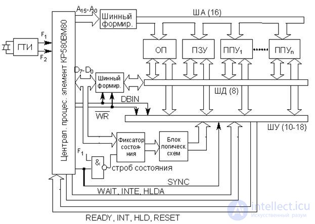
Fig.20.4. Simplified block diagram of a microprocessor system based on MP KR580VM80
Let us consider in more detail the process of executing a command. This process is divided into machine cycles , which are denoted M1 ... M5. The number of cycles in one team can be from one to five. In turn, each engine cycle consists of clock cycles, denoted by T1 ... T5. In one machine cycle can be from three to five cycles. This refers to 5 types of clock cycles, since in each clock cycle a certain action is taken to implement the machine cycle. At the same time, the number of cycles as time intervals can be significantly more due to T2 cycles, which will be discussed below. В каждом машинном цикле производится одно обращение к памяти или ППУ в разных вариантах. Каждый такой вариант обращения называется состоянием цикла. Всего в МП КР580 возможно 10 состояний машинного цикла. Это выборка первого байта команды, чтение из памяти, запись в память, чтение из стека, запись в стек, ввод из ППУ, вывод через ППУ, подтверждение прерывания, подтверждение останова, подтверждение прерывания при останове. При этом первым машинным циклом любой команды всегда является выборка первого байта команды.
Во всех машинных циклах первые три такта (T1,T2,T3) используются для организации обмена с памятью и ППУ. Такты T4 и T5 (если они есть) – для выполнения внутренних операций в МП. Таким образом, процесс выполнения команд состоит из стольких машинных циклов, сколько обращений к памяти или ППУ требуется для ее исполнения.
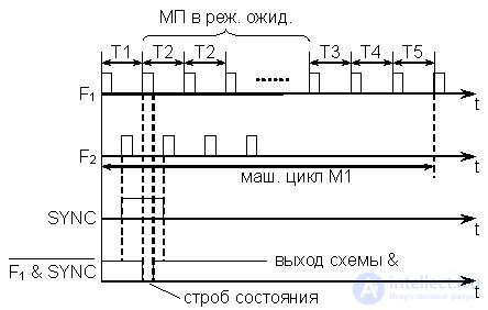
Рис.20.5. Временная диаграмма цикла М1
In fig. 20.5 представлена временная диаграмма цикла М1 из пяти тактов (первый машинный цикл любой команды). Отсчет тактов производится от положительных фронтов импульса F1. Действия процессора по реализации машинного цикла М1 состоят в следующем:
T1 – содержимое РС выдается на ША, адрес принимается памятью, где начинается чтение байта команды из ячейки.
T2 – проверяется наличие сигнала на входе READY (уровень логической 1). Этот сигнал подается на вход МП через интервал времени, достаточный для завершения процесса чтения из памяти. Если на входе READY сигнал отсутствует (действует логический 0), то МП устанавливается в режим ожидания , в котором каждый следующий такт рассматривается как T2 до тех пор, пока не появится сигнал READY. С приходом этого сигнала МП выходит из режима ожидания и переходит в такт T3.
T3 – байт с ШД принимается в МП и помещается в регистр команд (РгК).
T4 – происходит анализ принятого байта и выяснение потребности в дополнительном обращении к памяти. Если дополнительных обращений не требуется (команда однобайтовая и операнды находятся в регистрах процессора), то в этом же такте или с использованием дополнительного такта T5 выполняются предусмотренные командой микрооперации.
T5 – дополнительный такт.
Если требуется дополнительное обращение к памяти, то после T4 цикл M1 завершается и происходит переход к циклу M2.
Отметим, что КОП всегда находится в первом байте команды. Если команда двух- или трехбайтовая, то в остальных байтах находятся данные или адрес. Содержимое этих байтов помещается в аккумулятор или буферные регистры. Так, например, в команде MOV (запись аккумулятора в ячейку памяти) двухбайтовый адрес, который следует за КОП, помещается в регистровую пару WZ, а затем, при исполнении, он передается через мультиплексор непосредственно в РА и далее через буфер на ША.
В каждом машинном цикле в такте T1 по переднему фронту F2 МП выдает сигнал синхронизации SYNC, т.е. на выходе SYNC появляется уровень логической 1. Одновременно с этим сигналом в такте T1 МП выставляет на ШД 8-разрядное управляющее слово , которое несет в себе полную информацию о микрооперациях в текущем машинном цикле. Так, например, 1 в разряде D0 управляющего слова является сигналом подтверждения прерывания INTA. Наличие 1 в разряде D2 означает, что в данном машинном цикле на ША установлено содержимое указателя стека (регистр SP). Наличие 1 в разряде D3 означает, что МП в состоянии останова. В момент прихода импульса F1, означающего начало такта T2, на схеме "&" (рис. 14.6) вырабатывается импульс, называемый строб состояния . Этот строб разрешает запись управляющего слова с ШД во внешний регистр, названный на схеме фиксатор состояния .
Используя это слово или его часть, специальные логические схемы вырабатывают системные управляющие сигналы для обращения к памяти и ППУ. В общем случае фиксатор состояния и блок логических схем называются системным контроллером. Эти, а также некоторые другие вспомогательные схемы, в частности шинный формирователь, оформлены в виде специальной БИС КР580ВК28. Однако в простейших микроЭВМ часто требуются только 4 управляющих сигнала – R, W, IN, OUT. В связи с этим необходимость в БИС ВК28 отпадает, а используют какой-либо управляемый регистр и 2-3 логические схемы.
1. Принципы организации систем прямого доступа в память.
2. Способы организации доступа к системной магистрали при ПДП.
3. Возможные структуры систем ПДП.
4. Обобщённая цепочечная структура системы Bus Master DMA.
5. Структура шины арбитража ”n” системы bus master DMA цепочечного типа.
6. Организация обмена в режиме ПДП.
7. Принципы организации арбитража магистрали.
8. Упрощённая структурная схема микропроцессорной системы на базе МП КР580ВМ80.

Comments
To leave a comment
Computer circuitry and computer architecture
Terms: Computer circuitry and computer architecture