Lecture
In the process of running programs inside a computer or in the external environment, events may occur that require an immediate reaction from the processor. The reaction is that the processor interrupts the processing of the current program (the program being interrupted) and proceeds to the execution of some other program (the interrupting program) specifically designed for this event. Upon completion of this program, the processor returns to the execution of the interrupted program. The process in question is called program interruption and can be explained in fig. 19.1.
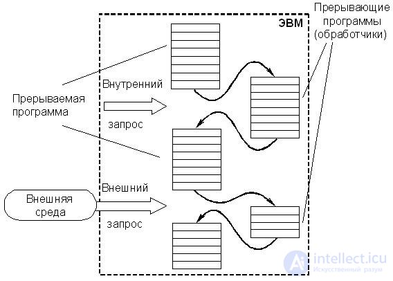
Fig.19.1. Program interruption
Each event requiring an interrupt is accompanied by a signal notifying the computer about it and called an interrupt request . Interruptions can be generated by internal and external events:
Internal - hardware failure, overflow of the bit grid, division by 0, exit from the set memory zone, attempt to access the forbidden memory zone, attempt to access the protected programs of the operating system, signal from the timer, etc.
External - a request from another computer, a message from the emergency sensors of the controlled process, an operator request, a request from the exchange operation, requests for servicing the keyboard, a mouse, etc.
In general, interrupt requests are generated by several processes developing in parallel in time, which at some point in time require processor intervention. Common to all these requests is that the moments of their receipt can not be foreseen. This essentially distinguishes the process of interruption from the process of transfer of control to the subroutine considered earlier, which occurs at previously known points of the main program.
The possibility of interruption is an important property of a computer, which makes it possible to efficiently use the performance of the processor and, above all, in organizing parallel operation of the processor and computer peripheral devices.
To efficiently organize the process of interruption and minimize the efforts of the programmer, modern computers are equipped with appropriate software and hardware, which are called the interrupt controller .
The interrupt controller in the general case is a fairly complex programmable device that requires appropriate initialization from the processor. During the initialization process, information about the discipline of servicing interrupt requests, the number of inputs used, the mode of interaction with the processor, etc. is loaded into the control registers of the controller. Usually, the controller is initialized when the computing system starts. However, most interrupt controllers allow reprogramming during the processing of a program, in particular, changing the discipline of servicing incoming interrupt requests. Structurally, interrupt controllers are executed as separate specialized LSIs, but in some cases they can be embedded in other devices of the computing system. The simplest interrupt controllers for small micro-computers are often built on general-purpose logic chips.
The main functions of the interrupt system are:
· Memorizing the state of the interrupted program and making the transition to the interrupting program;
· Restore the state of the interrupted program and return to it.
The term program (processor) state , strictly speaking, should be understood as the set of states of all storage elements (flip-flops, registers, memory cells) at the appropriate point in time (for example, after a microcommand, command, program). However, not all of this information is distorted when moving to another team or program, therefore, from the whole variety of information about the state of a program (processor), its most significant elements are selected, changing when switching to another team or program.
The state vector at each moment of time should contain information sufficient to start the program from the point corresponding to the moment of formation of this state vector. It is assumed that other information about the state of the processor nodes is either not significant or can be restored programmatically.
The state vector is formed in the corresponding registers of the processor, changing after the execution of each command. The sets of information elements that form a state vector differ from computers of different types and depend on the complexity of the processor. In the simplest processors, these sets are small. For example, in the processor КР580ВМ80 (I8080), the state vector consists of the contents of the instruction address counter (16 bits), the contents of the feature register (8 bits) and the contents of the battery (8 bits). In more complex processors, the state vector may contain a significantly larger number of elements.
Similarly, the initial state vector must contain all the necessary information for the initial launch of the program. In many cases, the initial state vector contains only one element — the starting address of the program being started.
When considering interrupt systems, the term interrupt vector is also widely used, which is nothing more than a vector of the initial state of the interrupting program (handler). The interrupt vector contains all the necessary information to go to the handler, including its starting address. Each interrupt level, and in simple computers, each interrupt input (peripheral device) has its own interrupt vector, which initializes the execution of the corresponding handler. Usually interrupt vectors are stored in specially allocated fixed memory cells with short addresses. Thus, to go to the appropriate interrupt program, the processor must have not only the interrupt vector, but also the address of this vector.
It should be borne in mind that the concept of interrupt vector is rather arbitrary, since in most cases the interrupt vector consists of only one element - the starting address of the interrupting program (handler).
If there are several sources of requests, a certain order of servicing incoming requests should be established, i.e. priority ratios should be established (discipline of service) . They determine which of several requests received at the same time is to be processed first of all, whether this request has the right to interrupt a particular program, etc. All this is included in the transition procedure to the interrupt program.
The effectiveness of computer interruption systems can be assessed according to very numerous characteristics, which reflect the characteristics of their technical implementation. However, to study the general principles of building an interruption system, it is sufficient to consider only the most generalized ones. These include the following characteristics.
· Total number of interrupt requests
The number of interrupt requests (sources of interrupt requests - TSP) varies significantly for computers of various types and can reach dozens. In systems of interruption of the radial structure, this concept may coincide with the concept of the number of inputs to the system of interruption. In the case of chained organization of the interruption system, these concepts do not coincide.
· Reaction time
The reaction time is defined as the time interval between the appearance of the interrupt request and the start of the execution of the interrupting program.
In fig. 19.2 shows a simplified time diagram of the interruption process under the assumption that the control of memory and return is entrusted to the handler itself. In this case, it consists of three parts - preparatory and final, which ensure the switching of programs, and the interrupting program itself, which performs the operations requested by the request. In addition, it is assumed that the request is represented by a potential level.
For the same request, the delay in the execution of the interrupting program (the processor of this request) depends on how many requests with the highest priority are waiting for service, therefore the response time is determined for the request with the highest priority. In fig. 19.2 it is denoted by t p .
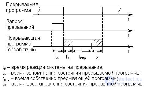
Fig.19.2. Simplified Interruption Process Timeline
· Interrupt latency (interrupt overhead)
The interruption delay (t ass ) is determined by the total time for memorization (t з ) and recovery (t в ) of the program (see fig. 14.6):
 .
.
· Interrupt depth
The depth of interruption determines the maximum number of programs that can interrupt each other. If, after the transition from the main program to the interrupting service, other requests are prohibited, then the system is considered to have an interrupt depth of 1. Depth is equal to n if sequential interruption is allowed to n programs. The depth of the interrupt is usually the same as the number of priority levels in the interrupt system. If the depth of interruption is not equal to 1, then this can be simplified by a diagram (Fig. 19.3). Here it is meant that the priority of interruptions increases at each following request. Systems with a high interrupt depth provide faster response to urgent requests.
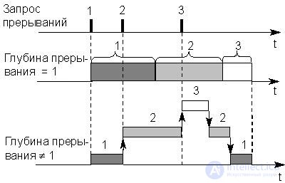
Fig.19.3. Simplified time diagram of the interruption process in systems with different depths
· Saturation interrupt system
If the request is not served by the time a new request comes from the same source (that is, the same priority), a phenomenon arises called the saturation of the interrupt system . In this case, part of the interrupt requests will be lost, which is unacceptable for normal operation of the computer. Therefore, the speed of the computer, the characteristics of the interruption system and the frequency of the arising requests must be strictly matched so that saturation is impossible.
· Valid program interruption moments
In most cases, interruptions are allowed after the execution of any current command, when the interrupt response time is determined mainly by the duration of the execution of a single command.
When a computer is working with fast technological processes in real time (i.e., in control circuits of real physical processes), this time can be unacceptably long. In addition, there are tasks that require an immediate response to an error detected, for example, by control equipment, in order to prevent the execution of an erroneously generated command code. Such situations are characteristic of military controllers.
In this case, the interrupt system implements the possibility of interruption after any clock cycle of the execution of a program command. However, this requires memorization, and then recovery of a much larger amount of information than in the case of an interruption after the end of the command, therefore such an organization of interruptions is possible only in a computer with a high-speed, high-performance, high-capacity memory.
· Number of interrupt levels
It has already been noted that in a computer the number of different sources of requests (causes) of an interruption can reach dozens and even hundreds. However, in some cases, many requests come from groups of similar devices that require the same interrupting program (handler) to be serviced. Requests from devices of the same type should be combined into groups, each of which will have its own interrupt request signal.
A level or class of interruption is a collection of requests that initiate the same interrupt program (handler).
Technically, such a union can be implemented in different ways. In fig. 19.4 shows a possible solution to this problem, provided that all incoming requests are recorded in the bits of the register of interrupt requests (RgZP).
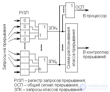
Fig.19.4. Dividing requests into interrupt classes
Requests from all sources are sent to the RHDP, setting its corresponding bits (flags) to state 1, indicating the presence of an interrupt request. Requests for the classes of interruption ZPK 1 -ZPk k form the elements OR, combining the discharges of the FrSP related to the corresponding levels. Another scheme OR forms the PCB that enters the processor's CU. It is formed at any request (the raised flag) of interruption.
Information on the actual cause of the interrupt (the specific source of the request) that spawned the request of this class is contained in the interrupt code, which reflects the state of the RHZP bits belonging to this interrupt class. During interrupt processing, these bits (the code they contain) are analyzed. This combination of interrupts into classes reduces the amount of hardware, but slows down the operation of the interrupt system. After transferring control to the interrupting program, the corresponding FGPC trigger is reset.
Specific technical implementations of interrupt systems have many options and depend on the type of processor used, the structure of the system interface, the purpose of the computer. At the same time, they are all complex combinations of a small number of basic interrupt system structures. Below are two main basic structures - radial and chain.
· Radial structure
The generalized structure of the radial-type interruption system is shown in Fig. 19.5 (ША and ШУ are not shown).
A characteristic feature of the radial structure is that each SPF (in the particular case of PU) is connected through LZP to a separate input of the interrupt controller. In this case, the number of connected PDAs is determined by the number of inputs to the interrupt system. Incoming requests, as a rule, are recorded in the discharges of the WFMD. Requests from an IPP can be represented by both the potential level and its differential, since they arrive at the controller on separate lines. However, the presentation of the request by the potential is more preferable, since the interruption system becomes more resistant to both interference and equipment failures. This significantly reduces the likelihood of missing a request from RRT.
The main advantage of such a structure is the simplification of the hardware IPP related to the maintenance of the interruption process, since their function is only to form the interrupt request signal, i.e. only the requester is needed.
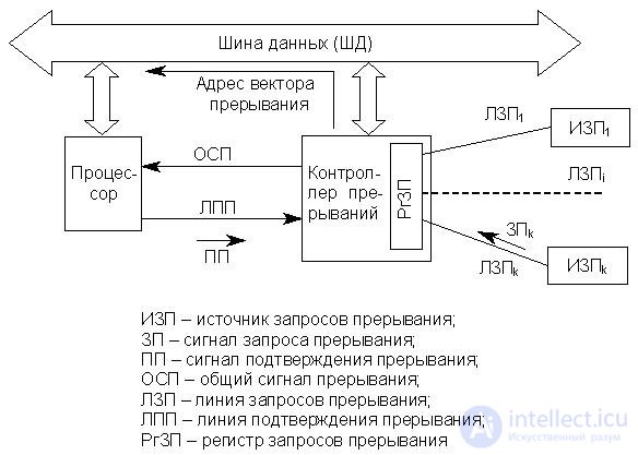
Fig.19.5. Radial structure of the interrupt system
· Chain structure
The generalized structure of the chain-type interrupt system is shown in Fig. 19.6 (ША and ШУ are not shown).
A characteristic feature of the chain structure is the fact that a set of TLs can be connected to one LZP. Each LZP corresponds to one entry to the interrupt system and has its own priority level. In contrast to the radial structure, requests from the IPP are always represented by the level of potential. Therefore, the output stages of the hardware query generation in each RPF are open-collector keys, combined according to the mounting scheme "or". This allows you to exclude the loss of requests simultaneously put up by different sources on one LZP. Interrupt requests that come from different LZPs and have different priorities can be recorded (as in the previous case) in the RGZP bits.
The main advantage of such a structure is an almost unlimited number of PSUs connected to one input of the interrupt system (one LZP) without slowing down the performance. However, the complexity and volume of the hardware supporting the interrupt system in each SPR increases significantly, which increases the cost of the interrupt system and the computer as a whole. In addition to the interrogator, each SPR must also contain hardware for generating the code of the address of the interrupt vector. And the equipment of the interrogator itself is also complicated. In addition, it is necessary to take measures to ensure that in the absence of any SPP, the distribution circuit of the PP signal does not open. This is provided either by a special slot contact design or by jumpers on the system board.
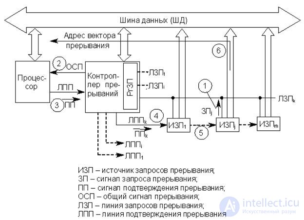
Fig.19.6. The chained structure of the interrupt system (the numbers denote the sequence of passing signals)
Despite the complication and rise in price of such interrupt systems as compared to radial ones, they are very widely used in computer systems of the most diverse architecture and purpose.
Specific implementations of transition procedures to the interrupting program largely depend on the structure of the interruption system and the type of processor used. Meanwhile, we can formulate some general principles for constructing these procedures.In any procedure of transition to the handler, the main place is taken by transferring the current state of the interrupted program to storage on the stack, and then loading into the registers of the interrupt vector processor, i.e. the initial state of the handler, which, as already noted, in most cases consists of only one element - the initial address. Interrupt vectors are stored in fixed OP cells, so the processor must first obtain the address of the corresponding interrupt vector. If there are several RPUs, the procedure for switching to the interrupting program also includes operations to identify the interrupt request with the highest priority.
It should be noted that there are absolute and relative priorities.
Absolute priority - a request that has an absolute priority, when it arrives, immediately terminates the program executed in the processor and initiates the execution of the corresponding handler.
Relative priority - a request that has a relative priority, when entering, is the first candidate for service after the completion of the current program.
It is the method of detecting the request with the maximum priority and the method of generating the address of the interrupt vector that distinguish interrupt handling procedures in systems of radial and chain structure. The following briefly discusses the main points of the transition to the interrupting program for both cases.
· Radial structure
В соответствии с рис. 19.5 все запросы от ИЗП фиксируются в разрядах РгЗП, который еще называется регистром флажков. При поступлении запроса в соответствующий разряд РгЗП записывается 1 (поднимается флажок). Дальнейшая последовательность операций по реализации процедуры перехода к прерывающей программе следующая.
1. При поступлении любого запроса (или нескольких запросов) в РгЗП формируется сигнал ОСП. Этот сигнал транслируется в процессор, а также инициирует процедуру поиска запроса с максимальным приоритетом, результатом выполнения которой является формирование кода адреса соответствующего вектора прерывания. Эта процедура может выполняться как программно, так и аппаратно. Некоторые варианты ее реализации рассматриваются ниже.
2. Процессор заканчивает выполнение текущей команды и посылает в контроллер сигнал "Подтверждение прерывания" (рис. 19.5).
3. В ответ на сигнал "Подтверждение прерывания" контроллер выставляет на ШД код адреса вектора прерывания.
4. Процессор считывает с ШД код адреса вектора прерывания, сохраняет в стеке вектор текущего состояния прерываемой программы (в простейшем случае только содержимое счетчика адреса команд) и осуществляет переход к прерывающей программе. Если вектор текущего состояния прерываемой программы автоматически сохраняется только частично, то операции по сохранению его остальных элементов возлагаются на обработчик (рис. 19.2, интервал времени tз).
· Цепочечная структура
В соответствии с рис. 19.6 к каждой ЛЗП (входу системы прерывания) может быть подключено множество запросчиков ИЗП, объединенных по схеме монтажное "или". Сигнал "подтверждение прерывания" распространяется по цепочке ИЗП, подключенных к одной ЛЗП. Распространение этого сигнала блокируется ИЗП j , выставившим запрос. Получив сигнал "Подтверждение прерывания", ИЗП j выставляет на ШД код адреса вектора прерывания. Таким образом, приоритет подключенных к одной ЛЗП устройств определяется положением ИЗП в цепочке распространения сигнала "Подтверждение прерывания". Это исключает необходимость выполнения процедуры поиска запроса с максимальным приоритетом среди ИЗП, подключенных к одной ЛЗП.
Если ЛЗП несколько, что обычно имеет место в реальных системах прерывания цепочечной структуры, в контроллере прерывания выполняется процедура поиска возбужденной ЛЗП с максимальным приоритетом, которая аналогична процедуре поиска запроса с максимальным приоритетом в системе радиальной структуры.
На основании вышеизложенного можно сформулировать последовательность основных операций по реализации процедуры перехода к прерывающей программе. При этом предполагается, что состояние возбужденных ЛЗП фиксируется в разрядах РгЗП, несмотря на то, что при потенциальном способе задания сигналов запросов прерывания его наличие не обязательно.
1. При поступлении любого запроса (или нескольких запросов) в РгЗП формируется сигнал ОСП. Этот сигнал транслируется в процессор, а также инициирует процедуру поиска возбужденной ЛЗП с максимальным приоритетом, результатом выполнения которой является выбор линии распространения сигнала "Подтверждение прерывания" (цепочки ИЗП).
2. Процессор заканчивает выполнение текущей команды и посылает в контроллер сигнал "Подтверждение прерывания" (см. рис. 19.6).
3. Получив этот сигнал, контроллер транслирует его на выбранную цепочку ИЗП.
4. ИЗП, имеющий максимальный приоритет среди устройств, выставивших запрос на выбранную ЛЗП, блокирует дальнейшее распространение сигнала "Подтверждение прерывания" и выставляет на ШД код адреса своего вектора прерывания.
5. Процессор считывает с ШД код адреса вектора прерывания, сохраняет в стеке вектор текущего состояния прерываемой программы (в простейшем случае только содержимое счетчика адреса команд) и осуществляет переход к прерывающей программе. Если вектор текущего состояния прерываемой программы автоматически сохраняется только частично, то операции по сохранению его остальных элементов возлагаются на обработчик (рис. 19.2, интервал времени t з ).
В простых системах прерывания цепочечного типа может присутствовать только одна ЛЗП. В этом случае отпадает необходимость выполнения процедуры поиска ЛЗП с максимальным приоритетом, которая, даже если выполняется аппаратными средствами, требует сравнительно больших временных затрат. Отпадает необходимость и в контроллере прерываний, поскольку сигнал с ЛЗП может непосредственно поступать на соответствующий вход процессора вместо сигнала ОСП. Такие системы прерывания являются наиболее динамичными даже при достаточно большом количестве ИЗП.
Уже неоднократно отмечалось, что обязательным компонентом процедуры перехода к обработчику является операция обнаружения наиболее приоритетного запроса прерывания (радиальная структура) или ЛЗП (цепочечная структура), которая в большинстве случаев выполняется в контроллере прерываний. Тем самым реализуется система приоритетных соотношений между ИЗП или цепочками ИЗП. Эта система приоритетных соотношений может быть либо фиксированной, либо изменяться программным путем в процессе обработки задачи. В соответствии с этим различаются системы прерываний с фиксированными приоритетами и с программно-управляемыми. Большинство контроллеров прерываний являются программируемыми и могут реализовывать систему как фиксированных, так и программно-управляемых приоритетов. Ниже рассматриваются некоторые варианты реализации процедур установления приоритетных соотношений обоих типов.
Рассмотрим только простейший случай установки приоритетных соотношений, состоящий в том, что уровень приоритета определяется порядком присоединения ЛЗП к входам системы прерывания, т.е. разрядам РгЗП. Пусть максимальный приоритет имеет вход с минимальным номером. В этом случае поиск ЛЗП с максимальным приоритетом сводится к поиску крайнего левого поднятого флажка в РгЗП. Процедуру поиска можно реализовать как программными, так и аппаратными средствами. В ряде случае эту процедуру называют соответственно программным или аппаратным полингом .
· Программный опрос РгЗП
Начало поиска инициируется сигналом ОСП. Программа поиска состоит из последовательности условных операторов, анализирующих разряды РгЗП, начиная с младшего. При обнаружении поднятого флажка управление передается обработчику. Если сигнал ОСП после выполнения обработчика не снимается, происходит повторный анализ разрядов РгЗП и поиск ЗП с максимальным приоритетом среди ЗП, оставшихся не обслуженными.
Программный полинг требует минимальных аппаратных затрат, поскольку выполняется процессором, а в качестве РгЗП можно использовать какой-либо управляемый регистр (т.е. БИС контроллера прерываний не требуется). Однако существенным недостатком метода является большое время поиска ЗП, особенно при большом количестве ЛЗП.
Для уменьшения времени поиска ЗП с максимальным приоритетом используют аппаратную реализацию алгоритма. Ниже рассматривается возможная структура такого устройства.
· Аппаратный циклический опрос РгЗП
Структурная схема устройства, реализующего аппаратный циклический опрос разрядов РгЗП, представлена на рис. 19.7. Устройство аппаратного полинга входит в состав контроллера прерываний и функционирует следующим образом.
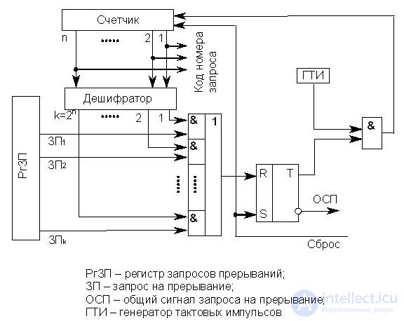
Рис.19.7. Схема устройства циклического опроса РгЗП
Опрос k линий запросов прерываний производится с помощью n-разрядного счетчика (2 n ≥ k), на вход которого поступают импульсы от ГТИ. Поиск начинается со сброса счетчика и установки T в состояние 0. При этом импульсы от ГТИ через схему & начинают поступать на вход счетчика. На выходах дешифратора, начиная с первого, последовательно появляются единицы. Это происходит до тех пор, пока не попадается возбужденная линия запроса прерывания, на которой тоже выставлена 1. В этом случае триггер T перебрасывается в состояние 1 и в процессор идет сигнал ОСП. Кроме того, прекращается поступление импульсов ГТИ на вход счетчика, т.е. завершается просмотр входов системы прерывания. Содержимое счетчика – код номера запроса (старшего по приоритету) используется для формирования адреса соответствующего вектора прерывания. После передачи управления обработчику счетчик и триггер сбрасываются в 0 сигналом "Сброс", и процедура опроса разрядов РгЗП возобновляется.
Рассмотренный метод опроса разрядов РгЗП существенно быстрее программного, но при большом числе ЛЗП время реакции системы оказывается достаточно большим.
· Аппаратный однотактный опрос РгЗП
Структурная схема устройства, реализующего аппаратный однотактный опрос разрядов РгЗП, представлена на рис. 19.8.
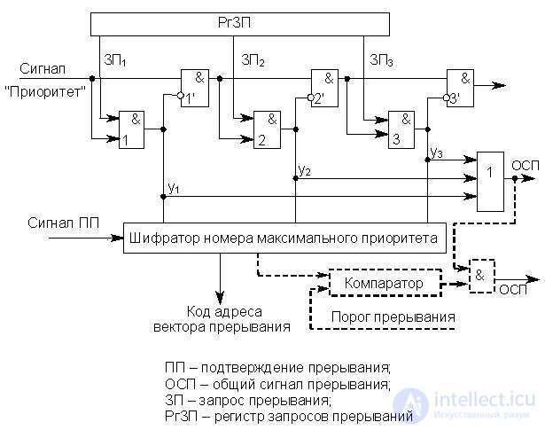
Рис.19.8. Схема устройства однотактного опроса РгЗП
Схемы подобного типа принято называть дейзи-цепочками , и в настоящее время они получили очень широкое распространение в различных устройствах ЭВМ. Схема функционирует следующим образом. Процедура поиска запроса с максимальным приоритетом инициируется сигналом "Приоритет", поступающим на цепочку последовательно соединенных схем &. При отсутствии запросов этот сигнал пройдет насквозь всю цепочку и сигнал ОСП не сформируется. (По-прежнему считаем, что максимальный приоритет имеет запрос с минимальным номером.) Пусть выставлен ЗП 2 . В этом случае распространение сигнала "Приоритет" блокируется & 2' , поскольку y 2 = 1. Кроме того, при обнаружении любого ЗП i формируется сигнал ОСП, поступающий в процессор, а шифратор по сигналу y 2 = 1 формирует код адреса второго (в общем случае i-го) вектора прерывания.
По сигналу процессора "Подтверждение прерывания" этот код передается в процессор, и происходит вызов соответствующего обработчика.
· Цепочка приоритетов
Как уже отмечалось, в цепочечной системе прерывания используется двухуровневая система приоритетов. Это приоритет ЛЗП и приоритет конкретного устройства в цепочке ИЗП, относящихся к одной ЛЗП. Приоритет ЛЗП определяется в процессе выполнения процедуры поиска наиболее приоритетного запроса (ЛЗП) в контроллере системы прерываний как радиальной, так и цепочечной структуры. Эта процедура описана выше. Приоритет устройства в цепочке ИЗП является фиксированным и определяется положением устройства на линии распространения сигнала ПП, т.е. ИЗП фактически образуют дейзи-цепочку. Таким образом, устройство, располагающееся в слоте, ближайшем к контроллеру прерываний, автоматически получает наивысший приоритет. Приоритет остальных устройств в цепочке убывает по мере удаления их слотов от контроллера прерываний. Приоритет устройства в такой системе прерывания можно изменить только путем перемещения устройства по линии распространения сигнала ПП, т.е. только перестановкой в другой слот.
При наличии нескольких наиболее приоритетных устройств такое распределение приоритетов становится недостатком, поэтому обычно используется несколько ЛЗП (4-8 линий). Наиболее приоритетные устройства в этом случае располагаются на всех ЛЗП в слотах, ближайших к контроллеру прерываний.
Во многих случаях приоритеты между прерывающими программами не могут быть зафиксированы раз и навсегда, т.е. требуется иметь возможность программно управлять приоритетами.
Существуют три основных метода реализации в ЭВМ систем программно-управляемых приоритетов – порог прерывания , маска прерывания и смена приоритетов . Первый используется, в основном, в системах прерывания микро-ЭВМ с простыми процессорами, второй – в более сложных ЭВМ с мощными процессорами, третий используется в вычислительных системах всех классов. В ряде случаев все три метода используются совместно. Ниже коротко рассматривается суть этих методов, позволяющих программным путем изменить дисциплину обслуживания ИЗП.
· Порог прерывания
Этот способ позволяет в ходе вычислительного процесса программным путем изменять уровень приоритета процессора (а следовательно, и обрабатываемой в данный момент программы) относительно приоритетов запросов источников прерывания (в основном периферийных устройств). Таким образом, устанавливается минимальный уровень приоритета запросов, которым разрешено прерывать программу, выполняемую процессором.
Порог прерывания задается командой программы, устанавливающей в регистре порога прерывания контроллера код порога прерывания . Вернемся к рис. 19.8, к его части, изображенной пунктиром. Ранее рассматривалось, как происходит выделение кода запроса с максимальным приоритетом. Затем этот код сравнивают с порогом прерывания (на компараторе), и, если он оказывается выше порога, вырабатывается сигнал ОСП и начинается процедура прерывания.
· Маска прерывания
Маска прерывания представляет двоичный код, разряды которого поставлены в соответствие запросам или классам прерываний (рис. 19.9).
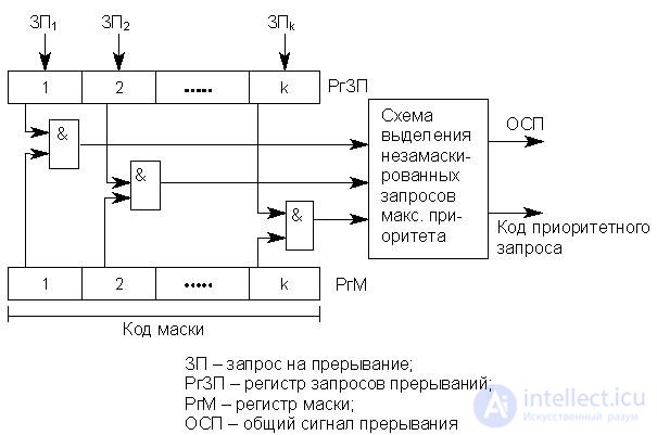
Рис.19.9. Схема реализации управления приоритетами с помощью маски прерывания
Маска загружается командой программы в регистр маски контроллера (РгМ). Состояние 1 в данном разряде маски разрешает, а 0 запрещает (маскирует) прерывание текущей программы соответствующим запросом. Таким образом, программа, меняя маску в РгМ, может устанавливать произвольные приоритетные соотношения между прерывающими программами без перекоммутаций ЛЗП. Каждая прерывающая программа может устанавливать свою маску. При формировании маски 1 устанавливается в разряды, соответствующие запросам (прерывающей программе) с более высоким, чем у данной программы, приоритетом.
На изображенной схеме элементы & выделяют незамаскированные запросы прерываний, из которых специальная схема, аналогичная дейзи-цепочке, выделяет наиболее приоритетный и формирует код его номера.
С замаскированным запросом поступают в зависимости от того, какой причиной он вызван: или он игнорируется, или запоминается с тем, чтобы осуществить затребованные действия, когда запрет будет снят.
· Смена приоритетов
В начале п. 19.3.1 было оговорено, что разряды РгЗП, а следовательно, и входы в систему прерывания имеют фиксированные приоритеты, причем максимальный приоритет имеет вход с минимальным номером. Между тем в большинстве контроллеров прерываний имеется возможность программным путем изменять приоритеты входов, т.е. изменять дисциплину обслуживания ИЗП. Существует относительно небольшое количество используемых на практике дисциплин обслуживания. Ниже рассмотрен один из наиболее распространенных вариантов дисциплины обслуживания – режим кругового (циклического) приоритета .
Этот режим характерен для таких применений, в которых ИЗП (цепочки ИЗП) имеют примерно одинаковый приоритет и ни одному из них нельзя отдать предпочтение. В то же время нормальное функционирование контроллера возможно только при наличии системы приоритетов. Выравнивание приоритетов ИЗП в этом случае осуществляется следующим образом.
Каждому входу контроллера (разряду РгЗП) при инициализации присваивается соответствующий приоритет. После поступления запроса и его обслуживания (выполнения соответствующего обработчика) приоритеты входов контроллера автоматически изменяются в круговом порядке таким образом, что последний обслуженный вход получает низший приоритет. Например, контроллер прерываний имеет 4 входа, приоритеты которых после инициализации убывают в следующем порядке: ЛЗП 1 , ЛЗП 2 , ЛЗП 3 , ЛЗП 4 . Пусть в текущий момент времени завершено обслуживание ИЗП 2 (радиальная структура). После этого приоритеты входов автоматически будут распределены в следующем порядке: ЛЗП 3 , ЛЗП 4 , ЛЗП 1 , ЛЗП 2 . После обслуживания очередного ИЗП произойдет аналогичная смена приоритетов. Возможны и другие схемы выравнивания приоритетов ИЗП.
Одной из модификаций режима кругового приоритета является режим адресуемого приоритета . Этот режим аналогичен рассмотренному выше, но допускает программное определение входа контроллера, которому назначен низший или высший приоритет.
Следует иметь в виду, что современные контроллеры прерываний в большинстве случаев содержат все или почти все механизмы реализации фиксированных и программно-управляемых приоритетов, рассмотренные выше. Набор используемых дисциплин обслуживания запросов прерывания зависит от разработчиков вычислительной системы, а конкретный режим обслуживания задается программным путем.
1. Принципы организации систем прерывания программ.
2. Состояние программы и вектор прерывания.
3. Основные характеристики систем прерывания.
4. Определение числа уровней прерывания.
5. Радиальная структура системы прерывания.
6. Цепочечьная структура системы прерывания.
7. Типы приоритетов прерываний.
8. Процедура поллинга.
9. Схема устройства однотактного опроса регистра запросов прерывания. Дейзи-цепочки.
10. Реализация программно-управляемых приоритетов.
11. Схема реализации управления приоритетами с помощью маски прерывания.

Comments
To leave a comment
Computer circuitry and computer architecture
Terms: Computer circuitry and computer architecture