Lecture
A multiplexer is a device that has several signal inputs, one or more control inputs, and one output. The multiplexer allows you to transmit a signal from one of the inputs to the output; however, the choice of the desired input is carried out by applying the appropriate combination of control signals.
Analog and digital [1] [2] multiplexers differ significantly in the way they work. The first electrically connect the selected input with the output (the resistance between them is small - on the order of units / tens ohms). The latter do not form a direct electrical connection between the selected input and output, but only “copy” the logical level ('0' or '1') to the output from the selected input. Analog multiplexers are sometimes called switches [3] or switches.
A device opposite to a multiplexer in its function is called a demultiplexer. In the case of using analog multiplexers (using keys on field-effect transistors), there is no difference between a multiplexer and a demultiplexer; such devices may be called switches.
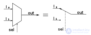
Schematically, the multiplexer can be represented as a switch that provides connection of one of several inputs (they are called informational ) to one output of the device. The switch serves a control circuit in which there are address inputs and, as a rule, permitting (gating).
The signals at the address inputs determine which specific information channel is connected to the output. If between the number of information inputs  and the number of address inputs
  valid ratio
  , such a multiplexer is called complete. If a
  , the multiplexer is called incomplete.
Permissive inputs are used to extend the functionality of the multiplexer. They are used to increase the capacity of the multiplexer, synchronize its work with the work of other nodes. The signals on the enable inputs can allow or block the connection of a specific input to the output, that is, they can block the operation of the entire device.
A decoder is usually used as a control circuit . In digital multiplexers, the logic elements of a switch and a decoder are usually combined.

The input logic signals X i are fed to the inputs of the internal switch and transmitted through the switch to the output Y. The input of the control circuit is the word of the address signals A k (from the English Address ). The multiplexer can also have an additional control input E (from the English. Enable ), which allows or prohibits the passage of the input signal to the output Y. In different types of multiplexers in the forbidden state of transmission on the input E at the output Y can be state 0 or 1.
In addition, some multiplexers can have a three-state output: two logical states 0 and 1, and the third state is a disconnected output (high-impedance state, often said, Z- state — output resistance is large, the output internal gate is disconnected from the output with a special internal key) . Translation of the multiplexer into the third state is made by feeding OE (from the English Output Enable ) logical 1, more often logical 0 - again, it depends on the model of the specific multiplexer.
Multiplexers can be used in frequency dividers, trigger devices, shifters, etc. Multiplexers can be used to convert parallel binary code to serial. For such a conversion, it is enough to submit a parallel binary code to the information inputs of the multiplexer, and to send signals to the address inputs in such a sequence that the inputs are connected in turn from the first to the last.
Multiplexers designate a combination of MUX (from the English. Multiplexer ), as well as MS (from the English. Multiplexer selector ).
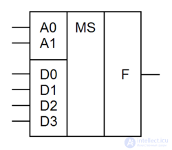
The multiplexer transmits a signal from one of the information inputs xi to a single output y, and the number of this input is equal to the decimal equivalent of the binary code at address inputs ai . If there is an input for enabling the output OE, then "0" on this input should transfer the output to the passive state (the last line of the table.5). Consider the 4 in 1 multiplexer, which has 4 information inputs and log4 = 2 address inputs.
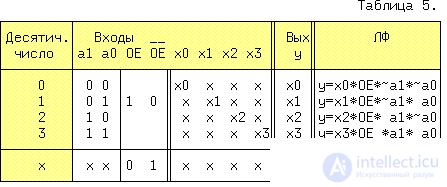
The value of x can take any value. The number of input variables is 7, and the truth table should have 128 lines. In Table 5, 64 source lines (taking into account the values x0 ... x3) and in the last line, the remaining 64 lines are packed in 4-x main lines. Analysis of the 0 line leads to the conclusion that y = x0, if a1 = 0 and a0 = 0 and OE = 1, regardless of the variables x1 ... x3. Therefore, for this input set, you can write: y = x0 * OE * ~ a1 * ~ a0. Similarly, y is written for the remaining three sets of variables. The general solution will then be:
y = OE (x0 * ~ a1 * ~ a0 + x1 * ~ a1 * a0 + x2 * a1 * ~ a0 + x3 * a1 * a0). (sixteen)Applying the axioms of double negation and duality to the right side of the equation we get:
------------------------------------ y = ~ (OE * x0 * ~ a1 * ~ a0) + ... + ~ (OE * x0 * a1 * a0). (17)Expression (17) corresponds to the scheme shown in Figure 18,
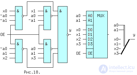
and its symbol and mechanical analogue in fig.19. If the combination inputs a1a0 = 11 (BIN) = 3 (DEC) are sent to the address inputs, then input D3 will be connected to output y, provided that OE = 1. The multiplexer may have an inverse output, as well as the third state of this output, which is marked on the diagram with a diamond with a cross bar.
Multiplexers are widely used in computing, for example, many of the outputs of microprocessors are "multiplexed", i.e. several internal sources of various signals are connected to the same output. These can be data bus lines and address bus signals transmitted sequentially in time, which reduces the total number of microprocessor pins. If we compare expressions (16) and (12), then we can see their identity, with fi = xi and OE = 1. Therefore, using a multiplexer with "n" address inputs, you can implement any LF with "n" variables, supplying multiplexer inputs fi values.

Comments
To leave a comment
Computer circuitry and computer architecture
Terms: Computer circuitry and computer architecture