Lecture
Measurement of a number of physical quantities, reflecting the parameters and characteristics of signals or electrical circuits, is carried out using instruments that are similar in construction to spectrum analyzers. These parameters and characteristics include nonlinear distortion and the associated changes in the shape and spectrum of signals that occur in circuits with nonlinear amplitude response. When passing along linear chains, the useful vibrations lose their sinusoidal shape (distorted) and higher harmonics appear in their spectrum.
The harmonic arising from nonlinear distortions can be investigated and measured using spectrum analyzers. There are several quantitative indicators of the level of nonlinear distortion. The most widespread such indicator as the nonlinear distortion coefficient (harmonic coefficient), which is the ratio of the mean square value of all higher harmonics of voltage (or current)
 Ur = U 22 + U 32 + ... + Un 2, (5.16) to the mean square value of its first harmonic, UKr = Ur / U1.
There are special devices that measure the coefficient
nonlinear distortion, called nonlinear distortion meters.
A simplified block diagram of an analog-digital nonlinear distortion meter is shown in Fig. 9.11.
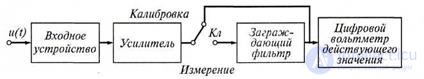
Figure 5.8 Simplified diagram of analog - digital nonlinear distortion meter
The measuring method of such devices is based on the method of suppressing the fundamental frequency of the signal under study. The input device serves to coordinate the measuring device with the source of the signal under study. Before measurement, the switch CL is set to Calibration. Then, with the help of an amplifier, the level of the investigated voltage is increased to such a fixed value at which the electronic digital voltmeter of the mean square value will be scaled in the values of the nonlinear distortion coefficient. At the same time, the mean square value of the voltage of the whole signal under study is measured.
 U = U 12 + U 22 + U 32 + ... + U n 2, (5.17)
Then switch the instrument CL is set to the Measurement position. Adjusting the fence filter, suppress the voltage of the main frequency (first harmonic U1). Full harmonic suppression U1, will be at the minimum reading of the device. In this case, the digital voltmeter shows the average quadratic value of the sum of the higher harmonic components of the signal Ur.Comparing the readings in the second and first cases, they find the harmonic coefficient:
Kr = Ur / U, (5.18)
Practically at the position of the switch KL Measurement measure the coefficient Kr1. The coefficient of harmonics Kr can be calculated by the formula:
 K r = 1 K - r K 1 r 21, (5.19)
With small non-linear distortions of the signal under study (Kr <0.1), the coefficients Kr and Kr1 differ by less than 1%. Typically, nonlinear distortion meters are used to measure the harmonic coefficient Kr in the range of 0.1 ... 30%. In this case, the operating frequency range can be from 0.01 kHz to 25 MHz or more.
1. How to write a mathematical expression for the harmonic coefficient?
2. Explain the algorithm for the practical determination of the harmonic coefficient.
3. Explain the circuit of the analog-digital nonlinear distortion meter.

Comments
To leave a comment
METROLOGY AND ELECTROradio-measurement
Terms: METROLOGY AND ELECTROradio-measurement