Lecture
The principle of operation of digital measuring devices is based on the discrete and digital representation of continuous measured physical quantities. A simplified block diagram of a digital voltmeter (Fig. 2.12) consists of an input device, an ADC, a digital readout device for the EAC, and a control device.
The input device contains a voltage divider; in AC voltmeters, it also includes an AC-to-DC converter.
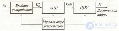
Figure 2.12 Simplified block diagram of a digital voltmeter
An analog-to-digital converter converts an analog signal to a digital one represented by a digital code. The process of analog-digital conversion is the essence of any digital device, including a voltmeter. The use in the ADC of digital voltmeters of a binary-decimal code facilitates the inverse transformation of a code into a decimal number reflected by a digital reading device. A digital reading device registers the measured value. Control device integrates all voltmeter nodes.
By type of ADC, digital voltmeters are divided into two main groups:
• code pulse (with bitwise balancing);
• time pulse.
Analog-to-digital converter of voltmeters convert a direct current signal into a digital code, therefore digital voltmeters are also considered as direct current devices. To measure the AC voltage at the input of a voltmeter, a converter is put into a DC voltage, most often an average rectified value.
Let's analyze the main technical characteristics of the average digital DC voltmeter:
• measuring range: 100 mV, 1 V, 10 V, 100 V, 1000 V;
• input resistance is high, usually more than 100 MΩ;
• threshold of sensitivity (other names - quantum or discretization unit) on the range of 100 mV can be 1 mV, 100 µV, 10 µV;
• number of characters (digital scale length) - the ratio I of the maximum measured value in this range to the minimum; for example: a measurement range of 100 mV at a quantization level of 10 µV corresponds to (100-10-6) / (10 • 10-9) = 104 characters;
• noise immunity.
Accuracy of digital voltmeters. The distribution of the error over the measurement range is determined by the limit of permissible relative, basic error characterizing the SI accuracy class:
 d U u K −1, (2.13) δ = ± с +
where u is the measured voltage; Uk - the end value of the range
measurements.
Speed performance. Modern ADC circuits used in digital voltmeters can provide very high speed, but for reasons of accurate recording of the result obtained with digital voltmeters, it decreases to about 20-50 measurements in 1s.
2.4.1 Code pulse digital voltmeters
In the code-pulse (with bitwise balancing) digital voltmeters, the principle of the compensation voltage measurement method is implemented. The block diagram of such a voltmeter is presented in Fig.
2.13.
The measured voltage U'h obtained from the input device is compared with the compensating voltage UК produced by the precision divider and the source of the reference voltage. The compensating voltage has several levels, quantized in accordance with the binary-decimal number system. For example, a two-digit digital voltmeter, designed to measure voltages up to 100 V, may include the following voltage levels: 80, 40, 20, 10, 8,4,2, 1 V.

Figure 2.13 Block diagram of a pulse-voltage voltmeter
A comparison of the measured U'x and the compensating UK voltages is carried out sequentially according to the commands of the control device. The comparison process is shown in Fig. 2.14.
The control pulses Uy at certain time intervals switch the resistances of a precision divider in such a way that voltages arise at its output: 80, 40, 20, 10, 8, 4, 2, 1B; simultaneously to the corresponding output of the precision divider connect the comparator. If UK> U'x, then the signal Ucp is sent from the comparator to turn off in the divider of the corresponding link, so as to remove the signal UK. If UK
After the end of the comparison process, the signal UK0D of the position of the keys of the precision divider is the code that is read by the digital reading device.
In fig. 2.14 for clarity, the process of encoding an analog voltage with an amplitude of 63V is shown, from which it can be seen that the code corresponding to this signal will be 01100011.
The process of measuring voltage in a code-pulse device resembles weighing on scales, which is why instruments are sometimes called “ equilibrium”. The accuracy of the code-pulse device depends on the stability of the reference voltage, the accuracy of the manufacture of the divider, the threshold of operation of the comparator device.
To create a normal noise immunity (60-70 dB), an anti-interference filter is placed at the instrument input; Therefore, such a device has good technical characteristics and is used as a laboratory.
The first digital devices were created by the method of weighing, but now time-pulse-type devices are more common.
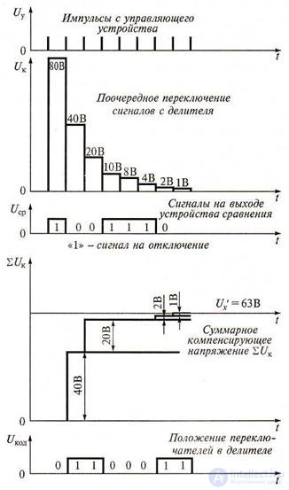
Figure 2.14 Graphs explaining the operation of a pulse-pulse voltmeter
2.4.2 Time-to-pulse voltmeters
The principle of operation of a voltmeter time-pulse (time) type is based on the ADC conversion of the measured voltage in a proportional time interval, which is filled with counting pulses, followed by a known stable repetition rate. As a result of this conversion, the discrete signal of the measuring information at the output of the converter has the form of a pack of counting pulses, the number of which is proportional to the level of the measured voltage.
There are several circuit solutions used when creating time-pulse voltmeters. Consider two such schemes.
Time-pulse voltmeter with a generator of linearly varying voltage. The block diagram of a time-pulse digital voltmeter and time diagrams explaining its work are presented in Fig. 2.15. This type of voltmeter includes an ADC with intermediate conversion of the measured voltage into a proportional time interval. The structure of the ADC includes: a generator of a linearly varying voltage GLIN; two comparison devices I and II; trigger T; logic AND; counting pulse generator; pulse counter and digital reading device.
The discrete signal of the measuring information at the output of the converter has the form of a pack of counting pulses, the number of which is N proportional to the input voltage U'x (ie, Ux) The linearly varying in time voltage UGLYN with GLIN is fed to the inputs I of both comparison devices. Another input of the comparator I is connected to the housing.
At the moment of time when the input voltage of the UGLIN = 0 at the input of the comparator I, a pulse U CI arises at its output conditionally fixing the zero level of the input signal. This impulse applied to a single input of trigger T causes a positive voltage at its output. The trigger is returned to its initial state by a UusII pulse, coming from the output of the comparator II, the UycII pulse arises at the moment of equality of the measured U'x and the linearly varying voltage UGLIN. The impulse UT formed at the trigger output is duration Δt = U'XS (here S is the conversion coefficient) and is fed to the input of the I circuit, to the second input of which the signal UGSI comes from the generator of counting pulses with the frequency ƒ0 = 1 / T0.

Figure 2.15. Digital voltmeter with time-pulse conversion: a - block diagram; b - time diagrams.
At the output of the circuit, And the signal Uf appears only if there are pulses UT and UGSI at both its inputs, i.e. counting pulses pass through the circuit And when a signal is present at the trigger output. The number of AND counting pulses passed through the circuit, N ≈ ∆t / T0, is counted by the counter and displayed on the meter's DAC indicator.
From the last two formulas we find the measured voltage:
U'x = N / (f0S), (2.14) In this voltmeter, the value of f0S is chosen to be 10m, where m = 1,2, 3, ..., (the number m determines the position of a comma in the digital reading) therefore the device directly shows the value measured voltage.
The considered cycle of the digital voltmeter periodically repeats. In this case, the return of the CLAY to its initial state and the preparation of the circuit for the next measurement is carried out automatically. By the same principle, digital voltmeters of alternating current are built. In these voltmeters, the AC voltage is pre-rectified and then fed to the comparator II.
The relation (2.14) does not take into account the discreteness errors due to the discrepancy between the time when the counting pulses appear and the beginning and end of the interval At. However, an even greater error is introduced by the nonlinearity factor of the S transform coefficient. The disadvantage of the time-to-impulse transform method is also its low noise immunity. Noise interference imposed on the measured voltage Ux changes it and, therefore, changes the moment of appearance of the pulse UusII determining the duration Δt of the counting time. Therefore, voltmeters constructed according to this scheme are the least accurate in the digital series.
Dual pulse time pulse voltmeters. The principle of operation of the voltmeter is similar to the principle of operation of the circuit with time-pulse conversion, with the difference that here during the measurement cycle T form two time intervals T1 and T2. In the first interval, the measured voltage is integrated, and in the second - some reference voltage. The duration of the measurement cycle T = T1 + T2 is obviously set to be multiple to the period of the disturbance acting on the input, which leads to an increase in the noise immunity of the voltmeters.
The block diagram of a digital voltmeter with double integration and timing diagrams explaining its operation are presented in Fig. 2.16.
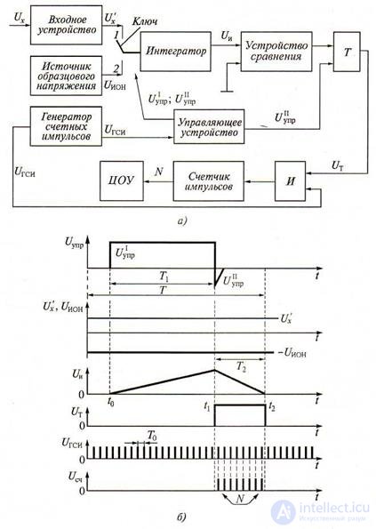
Figure 2.16 Digital Integrated Voltmeter:
a - block diagram; b - time diagrams.
The scheme contains an input device, a two-position key, an integrator, a source of reference voltage, a comparator, a trigger T, a generator of counting pulses, a control device, a logic circuit And, a pulse counter and a digital reading device.
At the beginning of the measurement cycle at t = t0, the circuit control device generates a calibrated pulse UI, with a duration of T1 = T0K , where Ta is the repetition period of the counting pulses; K - the capacity of the counter. At the moment of the appearance of the pulse front UI, the key is transferred to position 1, and a voltage U / x proportional to the measured voltage Ux is fed from the input device to the integrator . Then, on the time interval T1 = t1 - t0, the voltage U / x (proportional to the measured Ux) is integrated, resulting in an increasing voltage at the output
t 1
integrator will be: UI = ∫ U x dt. At the moment t = t1 the manager
t 0
the UI control signal transfers the key to position 2 and an exemplary negative voltage UION is supplied to the integrator from the reference voltage source. At the same time, the control signal UI control overturns the trigger.
Integration of voltage UION - is faster, since the circuit is set | UION│> U'X. The integration of the reference voltage continues until the output voltage of the integrator again becomes zero (with T2 = t2- t1). Therefore, during the time of the second
interval at the output of the integrator falling voltage is formed
t 2
U I = −∫ U ION dt . The duration of the interval
t 1
T2 integration is greater, the higher the amplitude of the measured voltage
U'x .
At time t = t2, the voltage UI at the integrator output becomes equal to zero and the comparator (the second input of which is connected to the housing) outputs a trigger signal, returning it to its original state. At its output, a pulse Ut of duration T2 is formed, which enters the input of the circuit I. At its other input, a signal UGSI is fed from the generator of counting pulses. At the end of the pulse UT coming from the trigger, the measurement process stops.
Conversion of the measured time interval T2 into an equivalent number of pulses N is carried out in the same way as in the previous method - filling the interval T2 with periodic pulses of the generator of counting pulses and counting their number with a counter. The number of impulses NUsc proportional to the measured voltage is recorded at the counter, and therefore at the center.
Ux:
t 1 t 2
∫ U x dt −∫ U ION dt = 0
t 0 t 1, (2.15) This expression leads to the following formulas:
T1 = T0K; T2 ≈ T0 N; U'XT1 = UIONT2, (2.16)
From the last equalities we get
U'x = UIONN / K, (2.17)
It can be seen from the above relations that the error of the measurement result depends only on the level of the reference voltage (and not on several, as in a code-pulse device). However, there is also an error of discreteness. The advantage of the device is high noise immunity, as it is integrating. On the basis of schemes with double integration, devices with a higher accuracy class than devices with GLINE are produced. Voltmeters of this type have a measurement error of 0.005 ... 0.02%.
Digital voltmeters of the highest accuracy class are created combined: in the schemes they combine the bitwise balancing methods and the time-pulse integrating transform.
Digital multimeters . The inclusion of a microprocessor digital voltmeter and additional converters in the circuit allows turning it into a universal measuring device - a multimeter. Digital multimeters measure DC and AC voltage, amperage, resistance of resistors, frequency of electrical oscillations, etc.
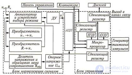
Figure 2.17 A digital voltmeter with a microprocessor
When used in conjunction with an oscilloscope, multimeters can measure time intervals (period, pulse duration, etc.). The presence in the electrical circuit of a microprocessor voltmeter allows automatic correction of measurement errors, auto-calibration and diagnostics of failures.
In fig. 2.17 shows an example of a digital voltmeter with a microprocessor. The main devices of the voltmeter are: microprocessor, ADC, signal normalization and control blocks.
The signal normalization unit with the help of appropriate converters leads the input measured parameters (AC and DC voltages, DC resistance, etc.) to a unified signal and which is fed to the input of the ADC. The latter usually operates by the method of double integration. The control unit provides the choice of operating mode for a given type of measurement, control of the ADC, the display and creates the desired configuration of the measurement system.
The basis of the control unit is a microprocessor, which is connected to other nodes through shift registers. The microprocessor is controlled using the keyboard located on the control panel or through a standard interface (interface block; interface) of the connected communication channel. The program of the microprocessor is stored in the ROM permanent storage device and is provided with the help of the random access memory RAM.
For measurements, built-in highly stable and precision resistive dividers of the reference voltage, a differential amplifier and a number of external elements (attenuator and mode selector, voltage reference block uop) are used. All pulsed and digital devices are synchronized with clock pulse signals.
1. What principle is implemented in code pulse digital voltmeters?
2. On what principle are voltmeters of pulse-type type built?
3. Explain the operation of a digital voltmeter with a microprocessor.
4. Explain the work of the digital voltmeter with double integration.

Comments
To leave a comment
METROLOGY AND ELECTROradio-measurement
Terms: METROLOGY AND ELECTROradio-measurement