Lecture
6.3.1 General Information
Characteristic attenuation, for which precise control must be observed at all frequencies, the equality ZH = Zс2, is measured much less frequently than the operating attenuation, which determines the mode of operation in the specified operating conditions.
Operating conditions are characterized by the resistance of the generator Z1 acting on the input of the quadrupole, and the load resistance Z2 included on its output. The magnitude of the working attenuation ar is the result of the comparison (Fig. 6.11) of the capacities P1 and P2, of which the first is taken for a given generator with some EMF E and with some internal resistance Z1 on a matched load connected to it directly (Fig. 6.11, a - the case considered as ideal), and the second power - at a given load of the four-port network Z2, if the same generator is turned on at its input (Fig. 6.11, b).
Since in the scheme 6.11, and U1 = E / 2, then, expressing ar through the ratio of the voltages, we obtain:
ap = ln | E / 2U2 | + (l / 2) ln | Z2 / Z1 | Np
ap = 20 lg | E / 2U2 | + 10lg | Z2 / Z1 | dB, (6.5) Characteristic resistances of the quadrupole for measuring the working attenuation do not need to know.
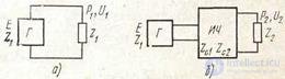
Figure 6.11 Power, compared when measuring the working attenuation:
a) P1; b) P2
6.3.2 Operating attenuation measurement methods
There are two main methods for measuring the working attenuation: 1) the “known generator” method, when a generator with a given internal resistance Z1 and some EMF E (indifferent for linear quadrupoles) is available measuring, and 2) the equivalent generator method, when the required value of generator resistance Z1 for any existing source is created artificially.
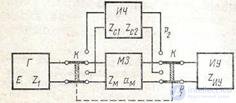
Figure 6.12 Measurement of working attenuation using a known generator.
a) The circuit with the “known generator” used, in particular, in the measuring consoles of the LAC, is shown in Figure 6.12. It makes it possible to measure ap both by the method of two readings by the difference of the levels, and by the method of comparison with the attenuation of the damping store,
characteristic impedance is ZM = Z1. In the first case
aP = p1-p2 + 101g | Z2 / Z1 |, (6.6)
where p1 is the level shown by the IU level meter in the lower position of the key K at the output of the attenuation store at its zero attenuation value (am = 0), and p 2 is the level shown at the quadrupole output (in the upper position of the key K). The magnitude 101g | Z2 / Z1 | found by calculation. In the second case, adjusting the attenuation of the store, one obtains the equality p1 = p2 and
aP = am + 101g | Z2 / Z1 |, (6.7)
The measurement results are correct if, in the lower position of the key, the resistance is RI ZIU = Z1, and in the upper position Z'IU = Z2, i.e., the given load resistance. When it is not possible to do this, you should change the circuit by switching on the output of the quadrupole the specified load resistance (and, if necessary, instead of the store, the specified generator resistance) and control the level of p2 (and, if necessary, p1) at high resistance of the IC.
In LAC measuring consoles, such schemes make it possible to measure the working attenuation with standard resistances of 600, 135 and 75 Ohms. In them, if necessary, the coordination of ZM with Z1 or Z2 with ZM can
produced using the front panel
matching transformers (aTr) and links (as.zv), then:
аР = р1 - р2 + аТр + as.zv + am + 101g│Z2 / Z1 |, (6.8)
Values of atR and as.zv are indicated in passports of consoles.
Measurements by the comparison method usually give more accurate results, since errors of readings on the PS scales are excluded, and the accuracy class of the MOH is usually higher than the PS.
b) Since Z1 and Z2 are usually set as purely active, a generator equivalent to the one specified with internal resistance Z can be created by turning on any output source of damping store with characteristic resistance ZM = Z1 when installed on it
attenuation of about 20 dB (and more). With such a large attenuation, the input resistance of the store on both sides with a negligible error can be considered equal to the characteristic. True, this significantly reduces the voltage removed from the output of the source.
A widely used other method of obtaining an equivalent generator is the so-called Z method (Fig. 6.12).
Comparing the diagrams in this figure is not difficult

Figure 6.12 Diagrams explaining the receipt of a generator with a given internal resistance according to the “Z method”
see that if a resistance equal to Z1 is turned on before the input of the quadrupole, then with the equality U '= U = E, the currents entering the quadrupole, and, consequently, the voltage at its output load Z2 for all these circuits will be the same (for the first circuit these currents are found according to Ohm’s law for the whole chain, and for the second and third - according to Ohm’s law for a section of the chain).
Thus, to create the specified operating conditions, it is sufficient to turn on the required resistance of the generator Z1 in series with the input of the quadrupole, and to accept the voltage at U at the output of any actual source (before the switched on Z1) supplying the created circuit; at the output of the quadrupole it is necessary to turn on the specified resistance Z2.
The measurement scheme of the working attenuation according to the “Z method”, which is mainly used for measuring individual elements of the path, is shown in Fig. 6.13. In the lower key presentation, the high-resistance indicator fixes the voltage U1 (or the voltage level p1) at the output of a consistently loaded damping store.
In the upper position of the key, the voltage U2 is controlled at a given operating load of the quadrupole Z2. If am = 0, then U1 = E / 2 and
ap = 201g (U1 / U2) + 10lg│Z2 / Z1│ = p1 - p2 + 10lg | Z2 / Z1 |, (6.9)
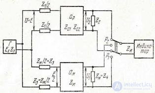
Figure 6.13. Scheme for measuring the working attenuation by the “Z method” using the damping store
If the measurements were made by the comparison method, then the store attenuation adjustment is achieved. Equality U1 = U2 (p1 = p2) and
aP = aM + 101g] Z2 / Z1 |, (6.10)
in general
aP = p1 - p2 + am + 10 lg | Z2 / Z1 |, (6.11)
6.3.3 Measuring working gain
The working gain Sp is equal to the working attenuation, taken with the opposite sign.
Therefore, if measured according to the scheme of Fig. 6.11, putting instead of an ICh amplifier, then using two readings with am = 0,
Sp = p2 - p1 - 10lg│Z2 / Z1│, (6.12)
The same would have been obtained if two samples were used according to the scheme shown in Figure 6.13 (for am = 0).

|
It is obvious that in order to use the comparison method in both schemes, it is necessary to rearrange the attenuation stores to another branch of the circuit sequentially with the measured amplifier so that the gain is compensated for by the attenuation of the magazine and one could get p1 = p2. Since, in addition, the value of the EMF should usually be limited so that its value does not extend beyond the linear portion of the amplitude characteristic of the amplifier, it is necessary to take into account and control the value of the EMF. As a result, from the scheme, for example, Fig. 6.11, the scheme of Fig. 6.14, for which:
Sp = p2 - p1 + am - 101g | Z2 / Z1│, (6.13)
At the same time, in order for the level at the input of the amplifier to be in the straight part of its amplitude response, the value of am should be chosen taking into account the voltage at the output of the generator (it is usually enough to check the latter using the generator output indicator).
If it becomes possible to make p2 = p1, then the comparison method and is carried out:
Sp = am - 10lg│Z2 / Z1│, (6.14)
Similarly, you can build and a scheme for measuring the gain of the "method Z".
It should be noted that the SP does not coincide, by definition (and therefore, in many cases, in magnitude)
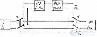
Figure 6.14 Measuring working gain with a known generator
voltage or power amplification, since for their control only the load resistance at the amplifier output is set, and the generator resistance is not taken into account (the output voltage (power) is compared with the input voltage, but not the one that would have happened if the generator worked directly on the load coordinated with it).
1. Write a formula to determine the working attenuation.
2. Methods of measuring the attenuation.
3. List the methods for measuring the working gain.
4. Write the formula for determining the working amplification.

Comments
To leave a comment
METROLOGY AND ELECTROradio-measurement
Terms: METROLOGY AND ELECTROradio-measurement