Lecture
An approximate check of the resistance of the wires (when a circuit is short-circuited at a neighboring station - the formation of a loop of two wires) is performed by ohmmeter-type devices - line testers.
DC bridges are used to accurately verify compliance with wire resistance. The insulation resistance of overhead lines (when insulating wires at an adjacent station) in many cases can also be tested with such bridges. To measure the insulation resistance of cable circuits, megohmmeters are used, or the comparison method (Fig. 8.1), which requires exemplary multi-resistance and a sufficiently sensitive galvanometer. The current I flowing through the measured Riz in position 1 of the key K2 is compared with the current I2 flowing through the reference resistance R0 in position 2 of the key K2. With relatively small resistances of the galvanometer and the current source, the ratio of currents can be expressed by the formula I1 / I2 = R0 / Riz. Since the currents I1 and I2 can differ greatly, it will be necessary to change the resistance value Rш of the shunting galvanometer. As a result, we get
Riz = R0 (α2n1 / α1n2), (8.1)
where α1 and a2 are deviations of the instrument arrow corresponding to currents I1 and I2, and n1 and n2 are the corresponding shunting coefficients (n
= Igalv / i).
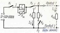
Figure 8.1. Measurement of insulation line insulation resistance by comparison method
The value of a is not read out immediately, but 1-2 minutes after switching on the voltage with the key K1, since the capacity of the line will take some time to charge. After the measurements, it is necessary to “discharge” the circuit through the resistance Rp by closing the key Kz. It is recommended to check the insulation resistance of the measuring circuit itself before the measurement by disconnecting the line; It should be greater than the measured resistance by at least an order of magnitude. If the insulation resistance of the cable circuit is comparable with the insulation resistance of the connecting wires RS.pr (measured separately), then the found working insulation resistance Rism is slightly less than the actual Riz which can be determined from the formula:
Riz = Rizm Rc.pr / (Rc.pr - Rism). (8.2) Measurement of the asymmetry of the wires by a direct current (often called ohmic asymmetry) is performed using the grounding loop method (Fig. 8.2). In this scheme, a bridge is connected to the bridge, consisting of two
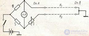
wires with resistances R1 and R2, forming the so-called "grounded stub" (loop), because the wires at the neighboring station are short-circuited and grounded.
Figure 8.2. Measurement of the asymmetry of the wires by the method of a grounded loop
Grounding resistances are included in the generator diagonal and should not affect the balancing. Usually take ra = rb, and then at equilibrium
R1 - R2 = rc, (8.3)
If R1 <R2, then the bridge (with ra = rb) cannot be balanced. In this case, change the wires in places when connecting them to the bridge.
The presence of earth currents can significantly impede the balancing of the circuit in fig. 8.2. With the constancy of the magnitude of these parasitic currents, you can resort to the method of false zero, when the arrow is not equalized to zero, the conditional, “false”, corresponding to the position of the arrow when the power is turned off and shifted relative to the zero mark due to interference. With varying interference, a third (auxiliary) serviceable wire between stations A and B is needed, which is switched on at both stations instead of ground.
Scheme fig. 8.2 is easily implemented in the PKP-2M, PKP-3, PKP-4, KM-61s, etc. devices. It is often called the bridge scheme with a constant shoulder ratio or the Varley scheme (and sometimes an extended loop scheme).
The battery voltage is taken small: (3–4 V) so that the resistance of bad contacts in the circuit does not change. When rc = 0, the change of wires in places should not change the indicator readings by their absolute value (see task 78).
Checking the working capacitance of the cable with direct current is carried out mostly by the ballistic method (Figure 8.3.) Or by the method of comparison (Figure 8.1.) In the latter case, you only need to mark R0 with the reference capacitor C0, and Riz with the measured working capacity Cx. Capacity required
Cx is determined from the expression
Cx = C0 (α1n2 / α2 n1), (8.4.)
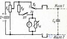
Figure 8.3. Measurement of cable capacity by ballistic method
Scheme fig. 8.3 works as follows: first, while pressing the ON button by moving the slider of the potentiometer Rp, set the required voltage U. Then, releasing the ON button, in position 1 of the key K1 “charge” the cable circuit. After that, the key K1 is transferred to position 2, and the circuit is "discharged" through a ballistic galvanometer BG. With a maximum deviation of the arrow a2 and a constant K of the galvanometer, the measured capacitance is determined from the expression
Cx = K α2 / n, (8.4) where n is the shunting coefficient.

Comments
To leave a comment
METROLOGY AND ELECTROradio-measurement
Terms: METROLOGY AND ELECTROradio-measurement