Lecture
Voltage and amperage are measured by direct estimation devices or instruments using the comparison method (compensators). By structural construction, devices measuring voltage and amperage can be divided into three main types:
• electromechanical; • electronic analog;
• digital.
2.1.1 Electromechanical devices
According to the physical principle of operation, which is the basis of the construction and design, electromechanical devices belong to the group of analogue measuring instruments, whose readings are a continuous function of the measured quantity.
Electromechanical devices directly assessing the measured physical quantity represent a class of analog-type devices with a number of positive properties: they are simple in design and in operation, have high reliability and respond to alternating current on the mean square value of voltage. The latter circumstance allows the measurement of the most informative signal parameter without methodological errors. Electromechanical devices are built according to a generalized structural diagram presented in Fig. 2.1.
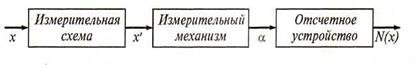
Figure 2.1 Structural diagram of an electromechanical instrument
The measuring circuit of an electromechanical device contains a set of resistances, inductances, capacitances and other elements of the electric circuit of the device and performs a quantitative or qualitative conversion of the input value x into the electrical quantity X, to which the measuring mechanism reacts. The mechanism converts the electrical quantity X into a mechanical angular or linear displacement α, the value of which is reflected on the scale of the instrument reading device, calibrated in units of the measured quantity N (x). For this, it is necessary that each and every value of the measured value corresponds to one and only one, definite deviation α. At the same time, the parameters of the circuit and measuring mechanism should not change when the external conditions change; ambient temperature, mains frequency and other factors.
Classification of electromechanical devices is carried out on the basis of the type of measuring mechanism. The most common in the practice of radio measurements the following systems: magnetoelectric, electromagnetic, electrodynamic, electrostatic.
These measuring systems are presented in table. 2.1, where also the formulas of the transfer function (scale equation) of the measuring mechanism and a number of its technical characteristics are given. In addition, placed in the table. 2.1 information and figures make the following explanation.
Magnetoelectric system. In this system, the measuring mechanism consists of a wire frame with a current flowing in it, placed in the field of a permanent magnet (magnetic circuit). The field in the gap where the frame is located is made uniform due to the special configuration of the magnetic circuit. Under the influence of the flowing current I, the frame rotates in a magnetic field, the angle of rotation α is limited by a special spring, therefore the transfer function (often called the scale equation) is linear:
α = I ψ0 / W , (2.1)
where ψ0 is the specific flux linkage determined by the frame parameters and magnetic induction; W is the specific opposing moment created by the special spring.
To extend the range of measurement of ammeters and voltmeters, shunts and additional resistances are used, which include, respectively, parallel and sequential measuring mechanisms in the diagrams of these devices.
Galvanometers A special group of current meters are highly sensitive magnetoelectric devices - zero-indicators, called galvanometers.
The task of galvanometers is to show the presence or absence of current in the circuit; therefore, they work at the starting point of the scale and must be very sensitive.
Galvanometers provide only conditional scale. Since the sensitivity of galvanometers is very high, their calibration characteristics are unstable and depend on a combination of external influencing factors.
Therefore, when releasing in production, sensitive galvanometers do not graduate in units of a measured physical quantity and they are not assigned accuracy classes (they are not normalized by accuracy classes).
As the metrological characteristics of galvanometers, they usually indicate their sensitivity to current or voltage and the resistance of the frame.
The sensitivity of galvanometers is expressed in millimeters or scale divisions (for example, Si = 109 mm / A). Such high sensitivity is achieved due to the special design of the device.
Modern galvanometers allow you to measure currents 10-5. Voltage
up to 10-4V.
Table 2.1 Electromechanical devices

Electromagnetic system. The principle of operation of this system is based on the interaction of the coil with a ferromagnetic core.
The ferromagnetic core is drawn into the coil at any polarity of the current. This is due to the fact that the ferromagnet is located in a magnetic field so that the field increases.
Therefore, the device of the electromagnetic system can operate on alternating current. However, it is low-frequency, since the inductive impedance of the coil greatly increases with increasing frequency.
The advantages of electromagnetic system devices are simplicity of design, the ability to withstand significant overloads, the possibility of calibration of devices intended for measurements in AC and DC circuits.
The drawbacks of the devices are high energy consumption, low accuracy, low sensitivity and strong influence of magnetic fields. Electromagnetic system devices are mainly used as shield ammeters and voltmeters of alternating current of industrial frequency. The accuracy class of panel devices is 1.5 and 2.3.
Electrodynamic system - the measuring mechanism contains two measuring coils: fixed and mobile. The principle of operation is based on the interaction of coils, the electromagnetic fields of which interact in accordance with the formula:
M bp = I 1 I 2 cos θ dM , (2.2) d α
where Mvr - torque; I1 is the current through the fixed coil; I2 is the current through the moving coil; θ is the phase shift between sinusoidal currents; M is the coefficient of mutual inductance of the coils.
Based on the electrodynamic mechanism, depending on the winding connection scheme, voltmeters, ammeters, wattmeters are performed.
The advantage of electrodynamic voltmeters and ammeters is high accuracy on alternating current.
The limit of the main reduced error may be 0.1 ... 0.2%, which is the best achievable indicator for measuring instruments of alternating current. Electrodynamic devices are used as exemplary laboratory measuring devices.
Electrostatic devices - the principle of the electrostatic mechanism is based on the interaction of electrically charged conductors.
The movable aluminum plate, fixed together with the pointer, moves, interacting with the fixed plate. Movement restricts the spring.
Electrostatic devices on the principle of the mechanism are voltmeters. The advantages of these devices: a wide frequency range (up to 30 MHz) and low power consumed from the measuring circuit. Instruments measure the mean square voltage value.
1. List the main systems of electromechanical devices and give the comparative characteristics of the parameters.
2. Why is the magnetoelectric mechanism operable only on direct current?
3. What systems of electromechanical devices are high-frequency?
4. Explain the block diagram of an electromechanical device.
5. How does an electromagnetic system device work?
6. The principle of the electrodynamic device.

Comments
To leave a comment
METROLOGY AND ELECTROradio-measurement
Terms: METROLOGY AND ELECTROradio-measurement