Lecture
5.1.1 General Information
The frequency f or period T refers to the basic parameters of any harmonic or periodic process. In general, the frequency refers to the number of identical events occurring per unit of time. For periodic, but not harmonic fluctuations, only the concept of a period is strictly true. However, in this case they often speak of frequency, meaning by this the inverse of the period.
The unit of cyclic frequency f-hertz (Hz) corresponds to one oscillation in 1s. Historically, in radio engineering, high frequencies are usually denoted by the letter f, and low frequencies by F.
It is known that the harmonic signal is written in the following form:
u (t) = Um cos (ωt + φ0) = Ucosφ (t), (5.1) where Um is the amplitude; ω - angular (circular) frequency; φ0 - initial
phase; φ (t) = ωt + φ0 is the complete (current, instantaneous) phase.
The angular frequency ω = 2πf is expressed in rad / s and is equal to the change in the current signal phase φ (t) per unit of time (second). The angular frequency is recorded for high and low frequencies, respectively, as ω = 2πf and Ω = 2πF. For harmonic signals (the frequency is determined by the number of transitions through the time axis (i.e., through zero) per unit time.
With frequency inconstancy, the concept of instantaneous angular frequency ω (t) = dφ (t) / dt = 2πf (t) is used, where f (t) is the instantaneous cyclic frequency. In this section, when describing frequency measurement methods, we mean its average value during the measurement time. There are also long-term and short-term frequency instability associated respectively with a constant change in frequency over long and short time intervals and with its fluctuation changes. The boundary between these instabilities is arbitrary and is set by specifying the measurement time.
The time interval Δt is the time elapsed between the moments of two successive events. Such intervals include, for example, the period of oscillation, the duration of a pulse or interval, determined by the spacing of two pulses.
The period T is the time interval through which the instantaneous values of the harmonic or periodic signal u (t) are regularly repeated. It follows that u (t) = u (t + nT), where n = 1, 2, 3, ....
For a harmonic signal, for example, u (t) = Umsin (2πt / T) = Umsinφ (t), the oscillation period T can also be defined as the time interval during which the signal phase φ (t) (in radians) changes by 2π .
The frequency f and the period of any periodic oscillation T are related by the formula f = 1 / T, and therefore the measurement of one quantity can be replaced by another. In practice, frequency is often measured.
The equipment for time-frequency measurements forms a single complex of devices, which makes it possible to carry out measurements with their direct connection to the State standard of frequency and time. This actually guarantees the possibility of fundamentally high measurement accuracy.
The main measuring instruments and means of frequency-time measurements are oscillographs, resonance frequency meters, digital frequency meters and time intervals, etc.
Depending on the part of the frequency spectrum and the permissible error for measuring the frequency, various measurement methods and techniques are used, based on the methods of comparison and direct assessment.
In comparison methods (resonant, heterodyne and oscillographic), the measured frequency is compared with the frequency of the source of exemplary oscillations. These methods are mainly used for the calibration of measuring instrument generators. For their implementation, an exemplary generator of higher accuracy and a device for comparing (comparing) frequencies are necessary.
Oscillographic methods include:
• determining the frequency using the Lissajous shape method;
• determining time intervals (period, pulse duration or a burst of pulses, etc.) using a calibrated oscilloscope sweep;
• Determination of frequency using brightness marks on a circular scan.
5.1.2 Digital frequency measurement method
Digital (discrete counting) frequency measurement method is implemented in digital frequency meters. The principle of operation of a digital frequency meter is based on measuring the frequency in accordance with its definition, i.e. on the count of the number of pulses for the time interval. These devices are convenient in operation, have a wide range of measured frequencies (from several hertz to hundreds of megahertz) and allow you to get the measurement result with high accuracy (the relative error of frequency measurement is 10 -6-10-9).
Since digital frequency meters are multifunctional measuring instruments, depending on their mode of operation, it is possible to measure not only the frequency and the ratio of two frequencies, but also time intervals (the period of the periodic signals and the interval specified by the time position of the two pulses).
The principle of measuring the frequency of a harmonic signal by a digital method is explained in Fig. 5.1, which shows a block diagram of a digital frequency meter operating in the frequency measurement mode, and time diagrams for its operation.
The analyzed signal of frequency fx is fed to the input device of the slave unit (see. Fig. 5.1, a), strengthening or weakening it to the desired value. The harmonic signal u1 removed from the output of the VU (see Fig. 5.1, b) is fed to the PI pulse shaper, which converts it into a sequence of short unipolar pulses u2 following the period Tx = 1 / fx and are called counting ones. The leading edges of these pulses practically coincide with the moments when the signal passes through a zero value on the time axis as it increases. Circuit design

Figure 5.1 Digital Frequency Counter:
a - block diagram; b - time diagrams
PI driver consists of a limiting amplifier and a comparator (Schmitt trigger).
The counting pulses u2 are fed to one of the inputs of the temporary BC selector, to the second input of which the strobe pulse u3 of rectangular shape and calibrated duration To> Tx is supplied from the UFU control and shaping device. Time interval That is called the counting time. The time selector opens the strobe - pulses u3, and throughout its duration passes a group (packet) several pulses u2 to the input of the counter of the midrange. As a result, a packet of Nx u4 pulses enters the counter from the time selector. The first counting pulse u2, which fell into the temporary gate, then the strobe pulse, is delayed relative to their front by the time Δtn, and the gate slice and the last counting pulse that appears before this slice separates the interval
ΔtK (see fig. 5.1, b).
From fig. 5.1, b it follows that
T0 = NxTx-ΔtH + ΔtK = NxTx-ΔtD, (5.2)
where Δtn and Δtk are the methodical absolute errors of discretization (discreteness) of the beginning and end of the interval That caused by the random position of the strobe pulse relative to the counting pulses u2, since the strobe and counting pulses are not synchronized; Δtd = Δ tHt- ΔtK is the total discreteness error.
Neglecting the error ΔtD in formula (5.2), we find that the number of pulses in a packet is Nx = T0 / TX = T0 and, therefore, the measured frequency is proportional to the number of counting pulses arriving at the counter,
fx = Nx / T0, (5.3)
For the formation of a strobe-pulse, short pulses with a period of To (not shown in the figure for simplicity) are received from the circuit including a quartz oscillator KG of an exemplary frequency fkw and a ten-day frequency divider of the pulse repetition with a division factor Cd (each decade reduces the frequency fkv to ten time). The period of the pulses at the output of the decade frequency divider and the duration of the strobe pulse are equal to the period of the signal at the output of the frequency divider, i.e. T0 = K d / fq. Therefore, the expression (5.3) is more convenient to present in the form:
fx = Nxfq / Cd, (5.4) The ratio fq / Cd can be discretely changed by variation of Cd ie due to the change in the number of decades of the decade frequency divider.
The counter counts the number of pulses Nx and outputs the corresponding code to the digital readout device of the center. The ratio fq / kd is chosen equal to 10n Hz, where n is an integer. In this case, the ESC displays the number Nx corresponding to the measured frequency fx in the selected units. For example, if a coefficient n = 6 is chosen due to a change in the CD, then the number Nx displayed on the ECC corresponds to the frequency fx expressed in MHz. Before starting the measurement, the VFU resets the counter to zero.
5.1.3 Digital method for measuring time intervals
The solution of many radio problems associated with the measurement of time intervals. Usually it is necessary to measure both very small (units of picoseconds) and very large (hundreds of seconds) time intervals. Time intervals can also be not only repetitive, but also one-time. There are two main ways to measure time intervals: oscillographic and digital.
Measurement of time intervals using an oscilloscope is carried out on the oscillogram of the voltage under study using a "linear" sweep. Due to the nonlinearity of the sweep, as well as large errors in the beginning and end of the interval, the total measurement error is a few percent. In recent years, time intervals are mainly measured by digital methods.
The principle of measuring the period of a harmonic signal using a digital frequency meter is explained in Fig. 5.2, where the block diagram of the device and the time diagrams corresponding to its work are given. The measurement of the time interval Tx by the digital method is based on filling it with pulses, following with the model period To, and counting the number Mx of these pulses during the measurement time Tx.
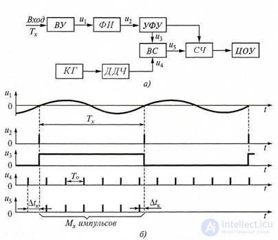
Figure 5.2. Digital frequency meter in the measurement mode of a sinusoid period: a - block diagram; b - time diagrams
The main elements of the device and their action were analyzed in the previous section.
In this case, the harmonic signal, the period Tx of which is to be measured, after passing through the input device of the VU (u1 is the output signal of the VU) and the PI pulse generator is converted into a sequence of short pulses u2 with the measured period.
A strobe pulse u3 of rectangular shape and duration Tx, which is fed to one of the inputs of the time selector BC, is formed from the device for forming and controlling them. To the second input of this selector, short pulses of u4 are fed with an exemplary repetition period To, formed by the decade frequency divider of the DPC from oscillations of the quartz crystal KG. The time selector transmits the number of M5 counted pulses u5 to the SCh counter during the time interval Tx equal to the duration of the strobe pulse u3 .. From figure 5.2, b it follows that the measured period:
TX = MHTO-ΔtD, (5.5)
where ΔtД = ΔtН- ΔtК is the total discretization error (discreteness); ΔtH and ΔtK are the sampling errors of the beginning and end of the period Tx.
Without taking into account the error ΔtD in the formula (5.5), the number of pulses received at the counter, Mx = TX / TO, and the measured period is proportional to Mx.
Tx = MHTO, (5.6)
The output code of the counter, sent to the digital reading device, corresponds to the number of counted pulses Mx counted by them, and the readout of the COI to the period Tx, since the repetition period of the counting pulses u5 must be chosen from the relation To = 10-n (n-integer). In particular, when n = 6, the VOC displays the number Mx corresponding to the period Tx expressed in microseconds.
1. List the oscilloscope frequency measurement methods.
2. What comparison methods are used to measure frequency?
3. Explain the digital frequency measurement method.
4. What is the digital method for measuring time intervals?

Comments
To leave a comment
METROLOGY AND ELECTROradio-measurement
Terms: METROLOGY AND ELECTROradio-measurement