Lecture
3.1.1 RC Generators
The technical characteristics of RC generators in the ranges of sufficiently low frequencies are significantly deteriorated due to the sharp increase in the values of inductances and capacitances of the oscillatory circuits and the corresponding sizes of inductors and capacitors. They are also difficult to tune in frequency over a wide range. Therefore, in the low-frequency harmonic oscillator measuring oscillators, frequency selective RC circuits are used as oscillatory systems and circuits of a positive OS. Such generators are called RC generators.
Usually, the RC generator includes a Win Bridge (Fig. 3.1, a), which performs the phase shift of the OC signal by 180 °. The generator is built on the basis of an amplifier, in which in a wide frequency range the transmission coefficient is real, and the phase shift φ = 2π is provided by Wien's bridge and signal inversion in the amplifier.
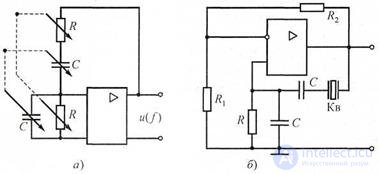
Picture. 3.1 Schemes of RC-generators with the Wien bridge: a - ordinary; b - with quartz stabilization
Frequency of harmonic oscillations in a RC generator with a Wien bridge
f = 2π1 RC , (3.1)
In fig. 3.1, b shows a simplified diagram of an RC generator with a Wien bridge in which, instead of one of the resistors, a Kv crystal oscillator is used, operating in voltage resonance mode.
3.1.2 Beat Generators
Generators of the audio frequency range (low-frequency generators) usually have a significant level of output power - up to 5 ... 10 watts. However, such power can be allocated only at a matched load, so the output transformer often includes a matching transformer, for example, at a load of 60, 600, 6000 Ohms. The readings of the electronic voltmeter of the output voltage will also be correct only when the generator load is matched. The generator frequency error can be reduced to less than one percent, its instability is of the same order. Increase frequency stability by using precision external elements (capacitors, inductors and resistors).
In the master oscillators sound frequencies use three methods of generation: direct; beat method; electronic modeling method.
To increase the frequency stability of sound generators, oscillating oscillators are often used on beats . The block diagram of the master oscillator contains two primary high-frequency
generator of fixed frequencies f1 and f2, a mixer and an intermediate frequency filter (Fig. 3.2).
The beating method consists in the fact that sound frequency oscillations are formed as a result of the impact on the nonlinear mixer element of two similar in frequency harmonic oscillations f1 and f2. In this case, the frequency f2 may vary from f1 to f1 + F, where F is the highest frequency of the operating range. At the output of the mixer receive combination frequencies, including the so-called intermediate frequency Fpch = f2 - f1. The oscillation of the intermediate frequency Fpch emit an intermediate frequency filter.
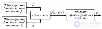
Figure 3.2 block diagram of the measuring generator on the beats
When creating measurement oscillators on beats, they take measures aimed at ensuring high frequency stability of the primary oscillators. As a rule, it is possible to periodically calibrate the generator frequency. The coefficient of nonlinear distortion of the generated oscillations is usually one tenth of a percent and is mainly determined by the quality of the intermediate frequency filter.
3.2.8 Digital low-frequency measurement oscillators
Digital low-frequency generators differ from analog ones in more effective metrological characteristics: high installation accuracy and frequency stability, low non-linear distortion (strictly sinusoidal form), and constant output level. Digital generators are more convenient than analogue ones in operation: higher speed, much easier to set the required frequency, more intuitive indication. Digital generators have the ability to automatically adjust the frequency of a predetermined program.
The action of digital generators is based on the principle of forming a numeric code with the subsequent conversion into a harmonic signal. In this case, the method of approximation of the output oscillation form is used.
The simplest type of approximation is a stepped one. It consists in the representation (replacement) of a sinusoidal oscillation by a voltage of a stepped form, which differs very little from a sinusoidal curve (Fig. 3.3, a). The approximated sinusoidal voltage u (t) = Um sin ωt is sampled in time (uniform sampling with a step Δt) and in the interval,
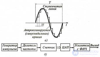
Picture. 3.3 Digital Low Frequency Generator:
and - step approximation of a sinusoid; b - block diagram
separating two neighboring points of time t i and t i + 1, the sinusoidal oscillation is replaced by a direct current voltage - a step whose height is equal to the value of the approximated voltage at the time t i t. e u (t i) = Vm sinωti. As a result of such a replacement, instead of a sinusoidal curve, a stepped line is drawn, as shown in Fig. 3.3, a.
With the available period T of the harmonic oscillation, the number of steps p per one period is determined by the discretization step: p = T / Δt. If, for technical reasons, the number of steps is given, then a change in the discretization step leads to a change in the period of the generated voltage, since T = pΔt. Considering that t i = i Δ t, the equation of a step curve is represented as v (iΔt) = Um sin (iωΔt) or with regard to p and ω = 2π / T:
u (iΔt) = Umsin (i2π / p), (3.2)
The step curve is the more closely approximated in shape to the sinusoid, the more the number of steps p is chosen. When this number is large, the step voltage can be considered as a low-frequency sinusoidal voltage, slightly distorted by high-frequency additive interference.
Spectral analysis of the voltage obtained by stepwise approximation shows that its spectrum contains the harmonic of the fundamental frequency and a number of higher harmonics. It turns out that the component with the p-1 number will be the closest to the main harmonic, the next one will be the p + 1 harmonic, then the 2p-1 and 2p + 1 harmonics, and so on.
For example, if p = 25 and the frequency of the voltage f of the main harmonic, the nearest harmonics will be the 24th, 26th, 49th, 51st harmonics, i.e. voltage frequency 24f, 26f, 49f, 51f. Such relations between the fundamental and higher harmonics make it possible to easily implement high-quality filtering, which sharply weakens the levels of higher harmonics, i.e. get a sinusoidal voltage characterized by a fairly small non-linear distortion factor.
The block diagram of the digital generator is presented in fig. 3.3, b. A pulsed crystal oscillator generates a periodic sequence of short pulses with a repetition period T. At the output of a frequency divider with an adjustable division factor g, a periodic sequence of pulses is obtained with a repetition period Δt = gT, which determines the sampling step. The pulses are fed into a meter with a capacity of p . The code combination, determined by the number i of pulses accumulated in the counter, will be transmitted to the D / A circuit. The latter produces a voltage corresponding to the number i, i.e. u (iΔt) = Umsin (i2π / p). Thus form a step of the approximated curve. When accumulating ripples, the counter overflows and resets to zero. With the advent of (p + 1) th pulse begins
the formation of a new period of a stepped curve. The frequency of the formed oscillation at a fixed number of steps p is adjusted by changing the sampling step Δt, which is achieved by changing the division factor g of the frequency divider.
1. How do measuring generators differ depending on the shape of the output signal?
2. How are generators divided by frequency characteristics?
3. What are the conditions for self-excitation of a harmonic oscillator?
What methods do they implement?
4. Explain the operation of the digital low-frequency generator.
5. Explain the work of the digital generator on the beats.

Comments
To leave a comment
METROLOGY AND ELECTROradio-measurement
Terms: METROLOGY AND ELECTROradio-measurement