Lecture
The amplitude-modulated (AM) signal can be analytically recorded as:
u (t) = Um (1 - m sin Ωt) sin ωt, (5.20) where u (t) is the instantaneous voltage value; Um is the unmodulated voltage amplitude; m is the amplitude modulation factor; ω is the angular frequency of the unmodulated carrier; Ω is the angular frequency of the modulating oscillation.
The amplitude modulation factor is determined by the expression:
m = ΔU / U, (5.21)
where U is the average voltage value; ΔU - maximum deviation
voltage from the average.
According to the oscillogram of the AM signal (Fig. 5.9), the coefficient m can be defined as:
m = U max - U min
U max + U min, (5.22)
Obtaining an oscillogram on an oscilloscope screen may be difficult due to the need to synchronize the sweep with the frequency of the modulating signal.
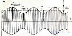
Figure 5.9 Amplitude Modulated Signal
The “trapezoid” method allows to circumvent this difficulty. In this case, the sweep is performed by a modulating sinusoidal signal from the G1 generator (Fig. 5.10, a). The coefficient of amplitude modulation (in percent) is determined similarly:
m = A - B ⋅100
A + B , (5.23)
Depending on the phase difference between the sweep voltage and the modulated voltage, images can be observed on the screen, the form of which is shown in fig. 5.10, b. At any phase ratio, the values of A and B remain unchanged.
In most cases, measurements of the amplitude modulation factor are made by the double detection method (Fig. 5.11). The modulated oscillation is supplied to the linear detector VD1,
loaded on a circuit consisting of a resistor R1 and a capacitor C1.
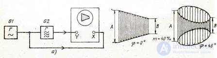
Figure 5.10 Trapezoid Method
When the time constant R1C1 is selected within TV <R1C1 <ТН where ТН is the period of the modulating signal and TV is the period of the RF oscillation, the voltage at the load will change in accordance with the change in the amplitude of the RF signal. The readings of the PV1 magnetoelectric device are proportional to the constant component Uo (Fig. 11.30). This instrument can also check whether the carrier amplitude remains unchanged during modulation and without modulation. The variable component of the voltage allocated to the resistor R1 is fed to an amplitude detector with a closed input (C2, VD2). The readings of the PV2 magnetoelectric device are proportional to the ΔU value.
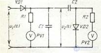
Figure 5.11 Dual Detection Method
m = ΔU / U0, (5.24)
Grading the PV2 instrument directly to the value of m is possible provided that Uo = const. This inconvenience can be eliminated if a logometer is used as an indicator (coils are turned on instead of resistors R1 and R2). It will directly measure the ratio of currents generated by the voltages Uo and ΔU, and, therefore, the amplitude modulation factor.
The double detection method can be used for any form of the modulating oscillation curve, since in this method the determination of the amplitude modulation factor ultimately reduces to a voltage change, its errors are caused primarily by voltmeter errors and are 3 ... 7% (device type C2 - 11 and others).
1. What is the amplitude modulation coefficient?
2. Determination of amplitude modulation coefficient by oscillographic methods.
3. Explain the method of double detection.

Comments
To leave a comment
METROLOGY AND ELECTROradio-measurement
Terms: METROLOGY AND ELECTROradio-measurement