Lecture
7
Measurement of parameters of components of electrical radio circuits
Topic 7.1 Measuring parameters of components with lumped parameters
7.1.1 General Information
Radio circuits whose physical dimensions are much smaller than the working wavelength are called chains with lumped parameters. The properties of such circuits are practically independent of the configuration of the leads (electrodes) of the active and passive elements and the size of the connecting wires. Radio circuits, the physical dimensions of which are commensurate with the working wavelength of the oscillations, refer to circuits with distributed parameters. Each element or connecting wire of this circuit has resistance (active, i.e. irrecoverable, power loss), inductance and capacitance. Such chains are called long lines or microwave paths.
Elements of the electronic circuit can be connected to two-terminal and two-terminal networks. A two-pole (single element or complex electrical circuit) has two terminals - the poles; quadrupole - a pair of input and a pair of output pins - four poles.
In electrical circuits with lumped parameters, linear components of general purpose are widely used: resistors, inductors and capacitors. Under certain assumptions, these elements are considered as linear passive two-terminal networks, characterized by certain ideal parameters - resistance R (the inverse of resistance - conductivity Y), inductance L, capacity C.
During measurements, it is not always possible to determine the value of one or another parameter corresponding to the ideal form of the element. The imperfection of the design and characteristics of the materials used is the cause of the parasitic parameters of the elements. So, along with the main parameter of the resistor - active resistance, it also has a certain inductance; the inductor, having inductance, has a parasitic capacitance and active resistance (loss resistance), etc.
Taking into account the parasitic parameters, a resistor, a capacitor or an inductor can be correspondingly characterized by some effective value of resistance, capacitance, inductance, which depend on the frequency of the currents flowing through them. Therefore, the effective parameters of the components must be measured at operating frequencies, if their influence on the measurement result cannot be neglected. It is also necessary to know the number of secondary parameters of these elements, for example: the quality factor Q
inductance coils, loss tangent δ of the capacitor, characteristic resistance ρ of the circuit, which allows you to more accurately determine the measured parameters.
The parameters of long lines, by analogy with chains with lumped constants, are running resistance, inductance and capacitance. However, unlike chains with lumped constants, these parameters do not have such a clear physical meaning and therefore they are not measured. At the same time, the elements of the microwave paths serve as analogues of two- and two-port networks, of which the chains with lumped constants consist. This analogy allows us to consider the parameters: EHF-paths as parameters of two- and two-port networks.
7.1.2 Measurement of active resistances by the method of ammeter and voltmeter
Measurement by the method of an ammeter and a voltmeter is reduced to the determination of the current or voltage in the circuit with the two-pole being measured and the subsequent calculation of its parameters using Ohm's law. The method can be used to measure active and impedance, inductance and capacitance. In fig. 7.1 shows the structural implementation of these methods when measuring active resistance. The measurement of active resistances is carried out at a direct current, while the resistor Rx can be included in the measuring circuit in two ways.
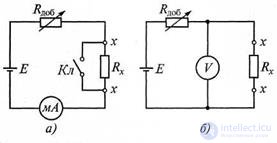
Figure 7.1 Measurement of active resistance method: a - ammeter; b - voltmeter
In the circuit with an ammeter (Fig. 7.1, a), the deviation of the readings of the milliammeter is proportional to the current
I =  R ext E + R x , (7.1)
and inversely proportional to the measured resistance Rx. According to this scheme, sufficiently large resistances are measured (from 1 Ω to 200 MΩ). Before measuring, the clamps are closed with the key Kl (thereby shorting the resistor Rx) and the variable resistor Rdo6 is set such a current so that the arrow deviates to the full scale, which corresponds to a point of 0 ohms.
For measuring small resistances (0.01 ... 100 Ohms) use a circuit with a voltmeter (Fig. 7.1, b). The readings of the voltmeter are determined by the formula:
 U = E R ext R + x R x , (7.2)
provided that Rdo5 >> Rx, U ≈ ERx / Rtob, i.e. There is a direct dependence of the voltage (voltmeter reading) on the measured resistance Rx. Before the measurement, the arrow on the device is combined with the mark “∞” with the clamps x open.
Both schemes lead to methodological errors in measuring ΔRX, depending on the internal resistances of the instruments. It is obvious that in the scheme shown in fig. 7.1, a, the methodological error of measurement is less, the smaller the internal resistance of the ammeter (with R A -> 0, ΔRx> 0), and in the circuit shown in fig. 7.1, b, this error is less, the greater the internal resistance of the voltmeter (with Rv -> ∞, ΔRx -> 0). So, the circuit shown in fig. 7.1, a, should be used to measure high resistances, and the circuit shown in fig. 7.1, b, - to measure small resistances. The accuracy of both methods is low - the measurement error is 1.5 ... 2%.
7.1.3 Ohmmeters
An ohmmeter is a direct indicating instrument for measuring electrical resistance in direct current.
The action of an ohmmeter is based on the application of Ohm's law: the voltage drop across an unknown resistance at a given current is measured or the current through an unknown resistance at a certain voltage is measured. In the simplest ohmmeters, a magnetoelectric mechanism of sufficient sensitivity is used as a reading device (full deflection current IK = 50 ... 100 μA). There are Ohmmeters with series and parallel connection of the measured resistance. A schematic circuit diagram of an ohmmeter of the sequential type is shown in fig. 7.2 In case of short circuit of the terminals A and B with the variable resistor R ext, a current is set in the circuit so that the arrow of the device PA1 deviates to the full scale. This is the “ohmmeter zero”. When connecting to the terminals AV of the measured resistance Rx, the current established earlier will decrease and the instrument needle will take another position.
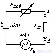
Figure 7.2 Ohmmeter circuit.
If we denote the relative value of the deviation of the instrument arrow a = I  Ik. and the ratio of the measured resistance to the internal resistance of an ohmmeter is A = R X / R OM, then the expression a = 1 / (1 + A) will determine the equation of the scale of an ohmmeter (Fig. 7.3). From the above expression it can be seen that for an infinitely large resistance Rx (open circuit) А → ∞ , а → 0, the current is equal to zero and the instrument arrow does not deviate. This position of the arrow on the scale is marked with ∞. The fact that the scale of the ohmmeter under consideration has the marks 0 and ∞ does not mean that they can measure any resistance. The scale of the device at the edges is highly compressed and practically only its middle part is used. The middle of the ohmmeter scale corresponds to its input resistance (for R x = R 0M, a = 0.5). This resistance determines the resistance limits measured by the device.
Usually R x lies in the range from 0.01 ROM to 100 R. If the upper R in and lower R is set to measure the resistance on a given ohmmeter scale,

Figure 7.3 The ohmmeter scale.
Measurement error: δ r = Δ A / A = ± k ( 1 + A) 2 (7.3)
where k is the relative reduced error (accuracy class
device PA1).
The measured resistance can be switched on not only sequentially, but also in parallel with the microammeter. In this case, the instrument scale is not reversed, but direct: “zero” is on the left, and “∞” is on the right, but still non-linear. Current through device P1:
Iism = IRx / (Rx + rвн) (7.4)
Taking into account that the total current in the circuit I = E / Rdob + R xrvn ./ ( R x + rin) can be obtained:
Iizm = E / Rdob + rvn + rvnRdob / Rx (7.5)
With a straight scale ohmmeter, it is more convenient to measure resistances commensurate with the internal resistance rvn of the device, i.e., smaller than ohmmeters with a reverse scale.
To extend the range of measurements used multi-limit ohmmeters. To do this, change the value of resistance Rdob 10, 100, 1000 times, M212, M371, as well as ohmmeters, which are part of universal devices, are multi-range ones. When measuring large resistances, it is necessary to increase the supply voltage.
7.1.4 Measurement with a logometer
The use of a magnetoelectric device - a logometer, which is found in laboratory measurement practice, allows to reduce the influence of the power source E on the accuracy of changes in active resistances. The device and circuit for switching on a magnetoelectric logometer are shown in fig. 7.6.
The logometer contains two frames rigidly fastened to each other, placed in an uneven field of a permanent magnet (Fig. 7.6, a), which is realized through a special configuration of pole pieces. Uneven fields are created so that the torques applied to the frames depend not only on the currents flowing in the frames, but also on the position of the frames in the magnetic field, i.e. M1 = ψ1 (α) I1; M2 = ψ2 (α) Ix, where I1 , IX
- currents flowing within; ψ1 (α), ψ2 (α) - values
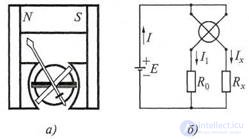
Figure 7.6 Magnetoelectric logometer:
and - the device; b - switching circuit
flux linkage magnets with their frames. The equilibrium position occurs at М1 = М 2; ψ1 (α) I1 = 2 (α) Ix and, therefore, the deflection angle of the moving system is defined as
α = F ( I 1 / I x ), (7.3)
For the scheme shown in Fig. 7.6, b
I 1 =  Rp + R 0; I x =
  Rp + Rx ; α = Rp + R 0 , (7.4)
where Rр - resistance framework; RQ - exemplary resistance. So according to (10.4), the readings of the logometer do not depend on the fluctuation of the supply voltage. The dependence of the readings on Rx allows you to create laboratory logometers with an error of measurement not exceeding 0.5%. The insensitivity of the gauge to fluctuations in the supply voltage also made it possible to develop a class of devices powered by generators, the rotor of which is rotated manually and sometimes used to determine the insulation resistance of telephone networks and in production.
7.1.5 Electronic ohmmeters
Analog-type electronic ohmmeters are performed on the basis of an inverting amplifier at an op-amp, covered by negative feedback using the measured resistance Rx (Fig. 7.7). The voltage at the output of the amplifier ohmmeter can be easily calculated by the formula:
Uout = - U R R 1 x , (7.5)
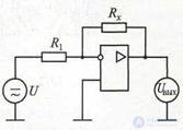
Figure 7.7 Diagram of an electronic ohmmeter
Since the output voltage in the circuit is linearly related to the measured resistance Rx, the instrument scale can be calibrated directly in units of resistance. The scale turns out to be uniform over a wide range and is practically independent of the external (mounted) elements of the amplifier. Measurement errors of electronic ohmmeters are significant - 2 ... 4%.
In instruments for measuring particularly large active resistances ( teraommeters ), the resistors R x and R1 are swapped, and the scale of the measuring instrument is reversed and the voltage
Uout = - U R R 1 x , (7.6)
The error in measuring the resistance with teraommeters reaches 10%.
Electronic resistance meters, built according to the above diagrams, are used to measure resistance and alternating current.
7.1.6 Bridge parameters measuring elements
Bridges are used to measure the parameters of the circuit elements.
Comparison of the measured value (resistance, inductance, capacitance) with an exemplary measure with the help of a bridge in the measurement process is carried out manually or automatically, using direct or alternating current.
Bridge circuits have high sensitivity, high accuracy, a wide range of measured values of the parameters of elements. On the basis of bridge methods, measuring instruments are designed, intended both for measuring any single quantity, and universal analog and digital devices.
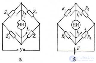
Figure 7.8 Schemes of four-shoulder bridges:
a - generalized; b - to measure the active resistance of NO - null indicator
There are several types of bridge circuits for measuring the parameters of R, L, C : quadruple, balanced, unbalanced and percentage. Management of these bridges can be carried out both manually and automatically. The most widespread are schemes of four-shoulder balanced bridges (fig. 7.8). A generalized block diagram of such a bridge is shown in Fig. 7.8, a . Resistances of the four-shoulder bridge are generally complex.
The equilibrium conditions of the four-shoulder bridge are determined by the equations:
Z1 Z4 = Z2 Z3, (7.7)
φ1 + φ4 = φ2 + φ3, (7.8)
where Z1, Z2, Z3, Z4 - modules of complex resistances; φ1, φ2, φ3, φ4 - their
corresponding phases.
To fulfill these equalities, it is necessary to have elements with adjustable parameters in the shoulders of the bridge. To ensure the condition of equality of amplitudes (7.7), it is most convenient to use reference adjustable resistance. The element providing the phase equilibrium condition (7.8) is the reference capacitor with a capacitance Co with low losses.
The four-arm balanced DC bridge for active resistance measurements is shown in fig. 7.8, b. An electronic or digital null-indicator of NOR is included in the diagonal of a balanced bridge. The current in the diagonal of the bridge at the time of measurement of active resistance is set to zero. For the equilibrium of the bridge, it is necessary that the equality RXR4 = R2Rз be fulfilled, whence the unknown resistance
R x = R 2 RR 34, (7.9)
To achieve equilibrium of a bridge with resistances, it is enough to have one adjustable parameter (for example, the resistor R4 resistance), as shown in Fig. 7.8, b. The limits of the measured resistances for these bridges range from 10 -2 to 107 Ohms; measurement errors - from fractions of percent to several percent, depending on the measurement range.
Shown in fig. 7.8, b. The bridge circuit can be partially implemented on digital elements. For this, an adjustable resistor is made in the form of a set of resistances made in accordance with the binary-decimal code. The resistances are alternately inserted into the shoulder of the measuring bridge until the bridge is balanced. The position of the keys is characterized by a code of the measured value, which then enters the digital reading device.
A series of AC bridge circuits for measuring inductance and Q-factor of the coils is presented in Fig. 7.9. They use harmonic current sources with voltage U and angular frequency ω. These four shoulder bridges provide the best balance. Equivalent equivalent circuits for inductors with losses can be sequential or parallel depending on the losses reflected by the resistance.

Figure 7.9 Bridge circuits for measuring inductances and their Q-factors with exemplary elements:
and - the coil; b - capacitor
The equilibrium condition of a four-arm bridge for the circuit shown in fig. 7.9, and, has the form:
R1 (Rx + jωLx) = R2 (R0 + jωL0), (7.9)
where Lx and Rx - measured inductance and resistance of ohmic
coil losses; Lo and R0 - exemplary inductance and resistance.
Equating the real and imaginary members of formula (7.9) we get:
Lx = L0R2 / R1; Rx = RoR2 / R1, (7.10)
Since the production of high-quality model coils causes certain difficulties, a capacitor is often used as an exemplary measure in AC bridges (Fig. 7.9, b). For this scheme
Rx + jωLx = R2R3 (l / R0 + jωC0), (7.11)
If in this equation we equate the real and imaginary parts separately, then we obtain the following expressions for determining the parameters of the inductance:
RX = R2R3 / R0; Lx = CoR2R3, (7.12)
Coil Q:
Qx = ωLx / Rx = R0ωC0, (7.13)
Для измерения емкости и тангенса угла потерь конденсаторов с достаточно малыми потерями применяют мостовую схему, представленную на рис. 7.10,а (последовательное соединение элементов Cx и Rx), а с большими потерями - на рис. 7.10,б (параллельное соединение элементов Сх и Rx).
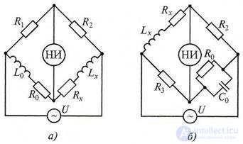
Рисунок 7.10 Схемы мостов для измерения емкости и тангенса угла потерь: а - с малыми потерями; б - с большими потерями
Условие равновесия для схемы, показанной на рис. 7.10,а, имеет вид:
R4[RX + 1/(jωСx)] = R2[Ro + 1/(jωС0)], (7.14)
Разделив вещественную и мнимую части последнего выражения, получаем следующие формулы для определения параметров конденсатора:
Cх = C0R4/R2; Rx = R2R0/R4, (7.15)
Тангенс угла потерь конденсатора:
tgδх = ωCхRx = ωC0R0, (7.16)
Для моста с параллельным соединением элементов Сх и Rx (см. рис.
7.10,б) условие равновесия имеет следующий вид:
R4Rx(1 + jωC0R0) = R2R0(1 + jωCxRx), (7.17)
From here
Сх = C0R4/R2; Rx = R2R0/R4, (7.18)
Тангенс угла потерь конденсатора при параллельной схеме его замещения:
tg δ = 1/(ωСхRх) = 1/(ωС0R0), (7.19)
Уравновешивание схем обеспечивают поочередным регулированием переменных образцовых сопротивлений или емкостей. Эту процедуру называют шагами, а количество шагов определяет сходимость моста. Мост с хорошей сходимостью имеет не более пяти шагов.
AC bridges are used at low frequencies: 500 ... 5000 Hz. When working at higher frequencies, measurement errors increase dramatically. The measurement error of an ac bridge determines the error of the elements forming the bridge, the contact resistances of the contacts, and the sensitivity of the circuit. AC bridges are more than DC bridges and are subject to interference and spurious connections between shoulders, shoulders and the ground, etc. Therefore, even with careful shielding of the bridge and taking other measures of protection, the errors in AC bridges are larger than those of DC bridges.
7.1.7 Resonant method for measuring element parameters
Резонансный метод измерения основан на настройке в резонанс колебательного контура, включающего образцовый и измеряемый элементы (индуктивности или емкости), и определении его резонансной частоты. Метод применяют для измерения индуктивностей и емкостей на высоких частотах, так как в области низких частот резонансные явления проявляются недостаточно резко, что не позволяет получить высокую точность измерения.
С помощью резонансных схем осуществляют измерение путем замещения, при котором один и тог же эффект (например, резонанс на фиксированной частоте) повторяют дважды: первый раз - с измеряемым элементом, второй - с мерой той же физической природы. За результат измерения принимают значение, равное величине меры при резонансе. Резонансные схемы удобны при точных измерениях относительно малых значений индуктивностей и взаимной индуктивности, емкостей и т.д.
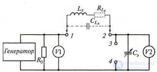
Рисунок 7.11 Упрощенная структурная схема куметра
Наиболее универсальным прибором для измерения параметров цепей резонансным методом является куметр (от латинской буквы Q -
характеристики добротности катушки индуктивности), в котором основной измерительной цепью служит последовательный резонансный контур. Упрощенная структурная схема куметра показана на рис. 7.11. Источником синусоидальных сигналов, подаваемых на последовательный резонансный контур, является генератор тока, нагруженный на малое активное сопротивление Ro ≈ 0,05 Ом. Частота выходных колебаний генератора может изменяться в широких пределах.
Уровень входного сигнала необходимо поддерживать постоянным (что контролируют по вольтметру V1).
При измерении индуктивности исследуемую катушку подключают к зажимам 1, 2. При этом резонансный контур будет образован катушкой измеряемой индуктивности Lx с активными потерями RLx и межвитковой емкостью ее проводов СLx а также перестраиваемой эталонной емкостью Сэ. Резонанс в контуре на заданной частоте устанавливают изменением величины емкости Сэ, эталонного конденсатора. Состояние резонанса контура определяют по вольтметру V2, отградуированному в значениях добротности Q. Измерение индуктивности Lx с учетом емкости СLx проводят на двух резонансных частотах, которые равны:

 f p 1 = 2π L x ( C 1 э C ; f p 2 = 2π L x ( C 1 э 2 + C Lx ) , (7.20) 1 + Lx )
где Сэ1 и Сэ2 - эталонные емкости на частотах fр1 и fр2.
Пусть соотношение частот fр1 = Кfр2, где коэффициент К - вещественное число. Тогда совместное решение уравнений (7.20) позволяет вычислить ранее неизвестные значения параметров Lx и CLx по формулам:
 L x = (2π f p 1) K 2(2 C − э 21− С э 1) ; С Lx = C э 2 K −2 С − э 11 K 2 , (7.21)
С помощью куметра можно также определять неизвестные параметры R, С, tgδc, подключая измеряемые резистор или конденсатор к зажимам 3, 4.
Погрешности измерения куметром параметров L, С, tgδc, К в зависимости от используемой схемы составляют 1...5 %. Причинами появления этих погрешностей являются: нестабильность генератора, наличие в контуре сопротивления Ro, неточность шкалы конденсатора эталонной емкости Сэ, погрешности измерительных приборов V1, V2, погрешность считывания показаний.
7.1.8 Цифровые средства измерения параметров элементов
Цифровые средства измерения параметров элементов электрических цепей чаще всего используют сочетание аналогового преобразователя, преобразующего определяемый параметр элемента в активную величину, и соответствующего цифрового прибора для измерения этой величины. Одним из методов измерения сопротивления, индуктивности и емкости является метод прямого преобразования их значений в пропорциональный интервал времени и измерение этого интервала путем заполнения счетными импульсами. Метод измерения называют методом дискретного счета.Второй способ цифрового измерения параметров элементов использует уравновешивающее преобразование сопротивления, индуктивности и емкости, основанное на сравнении измеряемой величины с образцовой.
При методе дискретного счета используют закономерности апериодического процесса, возникающего при подключенной запряженного конденсатора или катушки индуктивности с протекающим в ней током к образцовому резистору. При измерении активного сопротивления применяют процесс разряда образцового конденсатора через измеряемый резистор. При этом измеренный интервал времени функционально связан с преобразуемым параметром. Преобразователи отличают высокая точность, быстродействие, линейность функции преобразования, удобная для преобразования в цифровой код видом выходного сигнала.
Схема преобразователя сопротивлений, индуктивностей и емкостей в интервал времени (период меандрового напряжения) показана на рис.
7.12,а.
Измерительная цепь ИЦ интегрирующего типа с постоянной времени τх = R0CX (или RXCO, или Lх/R0 - рис. 7.12,б) питается выходным напряжением операционного усилителя ОУ, являющегося компаратором. Порог его срабатывания задают делителем R1 и R2. Временные диаграммы работы преобразователя параметров элементов приведены на рис. 7.12,в.
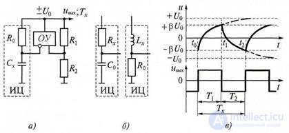
Рисунок 7.12 Преобразователь параметров элементов в интервал времени:
а - схема; б - измерительные цепи; в - временные диаграммы; ИЦ - измерительная цепь; ОУ - операционный усилитель
При поступлении в момент времени t0 на ИЦ с выхода ОУ напряжения Uo происходит его интегрирование измерительной цепью. Очевидно, что напряжение на инвертирующем входе ОУ:
u(t) = U0(1 + β)(l - et/τх)-βU0, (7.22)
где β = R2/(R1 + R2) - коэффициент передачи цепи положительной ОС.
При достижении этой функцией порогового значения + βU0 (момент времени t1) компаратор срабатывает и изменяет на выходе знак напряжения Uo на противоположный. Можно показать, что интервал интегрирования равен
 T 1 = t 1 − t 0 =π x ln11+−ββ , (7.23)
На следующем интервале времени Т2 = t2 - t1 происходит формирование развертывающей функции с противоположным знаком производной. Очевидно, что при равенстве значений положительного и отрицательного порогов срабатывания | + βU0| = | - βU0|,интервалы Т1 и Т2 равны. Период напряжения на выходе ОУ:
 T x = T 1 + T 2 = 2τ x ln11+−ββ , (7.24)
Этот интервал измеряют цифровым измерителем интервалов (или частотомером). Результат измерения периода Тх пропорционален значению определяемого параметра Rx (или Сх, или Lx);
In fig. 7.13 покачана структурная схема цифрового измерителя емкости и сопротивления, реализующая метод дискретного счета, а на рис.
7.14 - временные диаграммы к схеме.
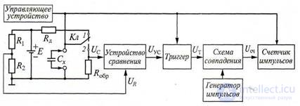
Рисунок 7.13 Структурная схема цифрового измерителя емкости и сопротивления
Перед измерением ключ Кл (рис. 7.13) устанавливают в положении 1 и конденсатор Сх заряжается через ограничительный резистор Rд до значения стабилизированного источника напряжения Е.
В момент начала измерения емкости t1 (рис. 7.14,а) управляющее устройство импульсом управления переключает триггер из состояния 0 в состояние 1, очищает предыдущие показания счетчика импульсов и переводит ключ Кл в положение 2 . Измеряемый конденсатор Сх начинает разряжаться через образцовый резистор Ro5p по экспоненциальному закону (рис. 10.10, б), который описывают уравнением:
U C = Ee −( t − t 1)/τ , (7.25)
где τ = RобрCx - постоянная времени цепи разряда конденсатора.
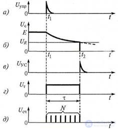
Рисунок 7.14 Временные диаграммы к рис. 7.13:
а - импульсы управления; б - процесс разряда конденсатора;
в- сигнал на выходе УС; г - сигнал триггера; д - импульсы на входе счетчика
At time t1, a single voltage pulse UT from the trigger output opens a coincidence circuit and the counter starts counting the generator clock pulses, which follow with a certain frequency f. Voltage Uc is fed to one of the inputs of the comparator, to the second input of which voltage is applied from a divider consisting of resistors R1 and R2. This voltage is equal to:
 U R = E R 1 R +2 R 2, (7.26) The resistances R1 and R2 are chosen such that when the capacitor discharges, the decreasing voltage Uc after the time τ becomes equal to the voltage UR. At time t2, when these voltages are equal, a voltage pulse Uyc arises at the output of the comparator, switching the trigger to the state in which the coincidence circuit closes with the falling edge of its pulse UT, and the counter stops counting the clock pulses (Figure 7.14, b - e ).
 Since at t = t2 the voltages are Uc = UR And τ = t - t1, then e - ( t 2 - t 1) / τ = R 1 R + 2 R 2 = e −1 = 2.7181 = 0.368, (7.27)
Thus, the voltage UR, taken from the divider R1 R2 has
a certain value (UR = 0.368E), which is achieved by the selection of resistors resistance. During the time interval τ = RroshСh the number of pulses goes to the counter
N = f τ, (7.28)
where f is the repetition frequency of the counting pulses.
Since τ = Ro5pCx, then for fixed values of the frequency f and the resistance Rsc
Cx = N / (fRo5p) = N / K1, (7.29)
Here the coefficient is K1 = fRo6p.
According to (7.29), the value of the measured capacitance is directly proportional to the number of pulses N received at the counter.
The presence of an exemplary Co6p capacitor allows you to measure the resistance of a resistor in a similar way:
Rx = N / (fCo5p) = N / K2, (7.30)
where the coefficient K2 = f Comp.
Digital measuring devices built by the discrete counting method are widely used in measuring electrical circuit parameters. The advantages of the method should include the relatively high accuracy of measurements; the measurement error by the digital method is 0.1 ... 0.2% and depends mainly on the instability of the resistances of the R1 R2, Ro5p resistors or the Co6p capacitor, the instability of the frequency f of the counting pulse generator, and the inaccuracy of operation comparison device. The disadvantages of such devices include the difficulty of measuring parameters at the operating frequency.
Along with the methods of direct conversion (discrete counting), in practice, methods of balancing conversion of measured values of resistance, inductance and capacitance are also used, based on a comparison of the measured value with the model value. Comparison of the measured value with the model is most often carried out by balancing the bridge measuring circuit, in one of whose arms include the bipolar circuit being investigated. A model element is introduced into the adjacent shoulder of the bridge, which is a set of quantized model measures corresponding to the weighting factors of the digits of the digital code used. By changing the parameters of the exemplary two-terminal device, the voltage in the measuring diagonal is equal to zero.
In fig. Figure 7.15 shows a block diagram of a balancing digital type DC bridge for measuring the active resistance of a resistor or other element with ohmic losses.
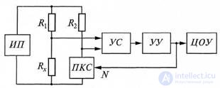
Figure 7.15 Block diagram of a balancing DC type digital bridge
Measured resistor Rx, model resistors R1 and R2 and
the code converter to the PKS resistance form a bridge, which is powered by a constant voltage source PI. The imbalance of the bridge is fixed by the comparison device US The control unit of the control system analyzes the output signal US and, depending on its sign, increases or decreases the value of the digital code N, issued to the PCB. Balancing is performed until the voltage in the output diagonal of the bridge becomes less than the sensitivity threshold of US. In this case, the measured resistance
Rx = R1 RPX / R1 = kPKCNR1 / R2, (7.31)
where RPKS - resistance PKS; kPKS = RPKS / N - coefficient
PKS conversion.
As follows from formula (7.31), the measurement result (it is recorded by the ECC) does not depend on the supply voltage. The measurement limits are selected by changing the ratio of the resistance of the resistors R1 and R2 of the positive feedback circuit. Digital balancing DC bridges provide an error in the measurement of parameters of about 0.01% and therefore they are widely used to accurately measure the resistance of resistors.
More complex in structure are AC bridges for measuring the impedance, inductance, and capacitance at a certain fixed frequency (usually about 1 kHz). These bridges perform balancing in two ways, i.e. produce a separate and independent balancing of the two components of the complex resistance Zх.
7.1.9 Earth Resistance Measurement
Different kinds of grounding (workers, intended to serve as the second wire of some circuit; protective - to eliminate the influence on the lines and equipment of induced dangerous and interfering voltages; auxiliary - for carrying out measurements) are controlled with alternating current, since the use of direct current leads to errors caused by polarization phenomena.
Since each ground has only one pin, it is necessary to have at least three earths (with resistances Rx, Rу, Rz) to determine the grounding resistance of any circuit. The simplest way to determine these quantities can be the three-sum method: by combining these resistances by two, we get Rxy = Rx + Rу; Rxz = Rx + Rz; Ryz = Ry + Rz, where you can find each of them. However, this method
gives too large an error if the resistances are very different from each other.
Most often, the ammeter and voltmeter method (Fig. 7.16), on which the device MS-08 is based, is used to measure grounding resistances. If the resistance of the voltmeter is large enough, then RX = UX / IX, where Ux is the voltmeter reading, and Ix is the ammeter.

Figure 7.16 Resistance Measurement Figure 7.17 Grounding Compensation is a method of measuring with an ammeter and a voltmeter against grounding
A compensation method for measuring grounding resistances is widely used; its scheme is shown in Fig. 7.17 (according to the similar scheme the device of type IZ works). By adjusting the resistance r, you can achieve a minimum volume of sound in the phone. This will mean that the potential at the contact of the engine of the potentiometer R created by the current I2 on the resistance r has the same magnitude and sign as the ground potential created by the current I1 flowing through the resistance Rx. In other words, I2 r = I1R2, i.e., these voltages compensate each other at each moment. So that such compensation could be achieved with different Rx transformer Tp is done
sectioned, with a variable transformation ratio, which makes it possible to change the strength of the current I2. The possibility of changing the phase of this current is shown in the diagram by crossing the wires of the secondary winding. If i1
= nI2, where n is the transformation ratio, then (in the absence of a current in the background body) Rx = r / n.
An important advantage of the compensation method is the lack of the need to take Ry and Rz approximately equal to Rx; they can be significantly different from Rx, since their values have practically no effect on the value of the value of the current I2 during compensation. It should, however, be borne in mind that when the values of Rx are too small, the measurement accuracy is low due to the inevitability of a certain phase shift in the transformer and grounding.
The measurement error of grounding resistances by the compensation method using an IZ instrument is 3–50% of the lower limit of measurements (there are three limits in the instrument: 0.02–1.5; 0.2–15; and 2 -
150 ohms). As for the normal values of the earth resistance, they can be different depending on the value of the ground and the number of wires introduced to the station.
1. What parameters of electrical circuits are considered concentrated and which are distributed?
2. List the main methods of measuring active resistances.
3. Give a brief description of the measurement methods of active resistances.
4. Equilibrium condition of a DC bridge.
5. Equilibrium conditions of the AC bridge.
6. Explain the work of the meter.
7. What methods of measuring parameters used in digital devices?
продолжение следует...
Часть 1 7.1 Measurement of parameters of components with lumped parameters

Comments
To leave a comment
METROLOGY AND ELECTROradio-measurement
Terms: METROLOGY AND ELECTROradio-measurement