Lecture
5.2.1 General Information
One of the main parameters of electrical oscillations, which determine the state of the oscillatory process at any given time, is the phase.
Along with the phase of one oscillation of interest is the ratio of the phases of two oscillations.
The need for measurements of these parameters arises in the study of amplifiers, filters, linear circuits, graduating phase shifters, removing the phase-frequency characteristics of various radio devices, etc.
The concept of “phase” characterizes harmonic (sinusoidal) oscillation at any particular point in time.
For harmonic oscillation, u1 (t) = Um1sin (ωt + φ1), having amplitude Um1 and circular frequency ω, the current (instantaneous) phase at any time t represents the entire argument of the function φ (t) = ωt + φ1, where φ1 is initial phase.
The phase shift Δφ of two harmonic signals of the same frequency u1 (t) = Um1sin (ωt + φ1) and u2 (t) = Um2sin (ωt + φ2) is the modulus of the difference between their initial phases.
Δφ = | φ1-φ2 |, (5.7)
It is generally accepted to call the quantity φ1-φ2 the phase difference of two signals. If the initial phases of φ1 and φ2 signals remain unchanged, then the phase shift Δφ does not depend on time.
For two harmonic oscillations with different circular frequencies ω1, ω2 and initial phases φ1, φ2, for which the zero values of the amplitudes at the transition through the abscissa axis are shifted by the time interval τ, the phase difference:
Δφ = (ω1 - ω2) τ + φ1 - φ2, (5.8)
For non-harmonic oscillations, the concept of a phase shift is replaced by the concept of their shift in time.
In this case, measure the time delay of one signal relative to another.
Depending on the specific measurement task and the frequency range in which measurements are made, the requirements for the accuracy of phase shift measurement can vary from fairly rough measurements (with measurement errors of 1 ... 5 °) to very accurate (0.01 °).
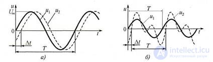
Figure 5.3. Graphs of two signals with the same periods: a - harmonic; b - harmonic and non-harmonic
Measuring the phase difference of oscillations with different frequencies is rarely of practical interest. Therefore, they usually solve the problem of measuring the phase difference of two harmonic oscillations with equal frequencies. In this case, the phase shift is conveniently represented as a dependence on the shift of signals in time Δt, corresponding to their identical phases. In particular, for two harmonic signals u1 (t) = Umsinωt and u2 (t) = U / msinω (t - Δt), having the same period T = 2π / ω (Fig. 5.3, a), the phase shift in radians:
∆ϕ = ω∆ t = 2π∆ t
T , (5.8)
Two signals with the same frequencies are called in-phase, quadrature and antiphase if the phase shift between them is 0, π / 2 and π, respectively. As applied to periodic harmonic and non-harmonic signals (Fig. 5.3, b) and two non-harmonic signals with the same period T, the concept of their shift (delay) in time Δt is used.
The phase shift measurement is performed with devices called phase meters, and phase shifters are used as shift measures, i.e. linear quadrupoles in which the output signal is shifted in phase relative to the input. Phase shifters are adjustable and unregulated.
To measure the phase shift, various measurement methods are used: oscillographic, compensation, phase-to-time conversion, digital (discrete counting), frequency conversion. Instruments for phase shift measurements that implement the listed methods (except oscillographic ones) are represented by analog and digital electronic phase meters, providing measurements in the range from infrasonic to high frequencies.
5.2.2 Oscillographic methods for measuring phase shift
a) Linear scan method
The considered method is realized when two signals are simultaneously observed on the screen (see Fig. 5.4, a). The linear sweep method consists in applying voltages u1 (t) = u1 and u2 (t) = u2 to the channels of the vertical deviation of a two-beam or two-channel oscilloscope (to inputs Y1 and Y2) and the subsequent measurement of the intervals
Δt and T. Apply and single-beam oscilloscope (Fig. 5.4), if
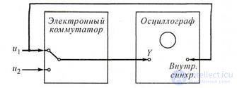
Figure 5.4 The linear sweep method
input Y feed the test signals alternately through
high-speed electronic switch. The electronic switch is periodically switched using pulses of the "meander" type, coming from the generator and following with a frequency F ≥ 25 ... 100 Hz. In either version, the horizontal scans of the oscilloscopes (internal sync.) Must be synchronized with one of the signals under study. It is useful to equalize the amplitudes of both input voltages before measurement.
Measuring the time intervals Δt and T (Fig. 5.4), calculate the phase shift of the signals in radians using the formula:
360 ° ∆ t
∆ϕ =
T , (5.9)
With this method of measurement, the error in measuring the phase shift Δφ is ± 5 ... 7 ° and is caused by the nonlinearity of the sweep, the inaccuracy of measuring the intervals Δt and T, as well as errors in determining the position of the time axis.
b) Sinusoidal sweep method or ellipse method
This method can be implemented using a single-beam universal oscilloscope when a single signal is applied to the input Y, and the second to the input X of the beam deflection. In this case, the oscilloscope sweep generator must be turned off. Let the voltages under study be simultaneously applied to the X and Y inputs of the oscilloscope: u1 (t) = u1 =
Um1 sinωt and u2 (t) = u2 = Um2 sin (ωt + φ), for which the phase shift Δφ = φ (the argument t is omitted everywhere for the simplicity of the formulas for u1 (t) and u2 (t)). The instantaneous deviations of the electron beam on the screen horizontally and vertically are:
x = hxUm1 sinωt = asinωt, (5.10) y = hyUm2sin (ωt + φ) = bsin (ωt + φ), (5.11) where the coefficients hx, hy are respectively the sensitivity of the oscilloscope to the deflection of the electron beam horizontally and vertically; a = hxUm1, b = hyUm2 amplitude of the beam deflection.

Figure 5.5 To the measurement of the phase difference by the method of ellipse
The electron beam will draw an ellipse on the oscilloscope screen (see fig. 5.5).
Let the amplitudes of the deviations of the voltages at the inputs X = Y. This condition is easily fulfilled by feeding the investigated voltages alternately to the inputs of the channels of the vertical and horizontal deviations of the oscilloscope. Adjusting the gains of the channels, achieve equal deviations of the beam. If a = b, the measured phase shift is related to the dimensions of the ellipse by the following expression: tg (Δφ / 2) = A / B,
where - A - small, B - major axis of the ellipse.
Thus, it is necessary to measure the small A and large B axis of the ellipse and calculate the phase shift using the formula:
Δφ = 2arctg (A / B), (5.12)
The ellipse method does not allow to unambiguously determine the phase shift in the range of 0 ... 3600. Ambiguity of measurement takes place for phase shifts:
0 <Δφ <90 ° and 270 ° <Δφ <360 °;
90 ° <Δφ <180 ° and 180 ° <Δφ <270 °; Δφ = 90 ° and Δφ = 270 °.
To obtain the correct measurement result of Δφ, it is necessary to apply the signal I2 to the Y input of the oscilloscope through the phase shifter, which creates an additional phase shift of 90 °. By changing the waveform can be concluded about the value of Δφ.
The error in measuring the phase shift between sinusoidal signals using the ellipse method is ± (2 ... 5) °. It depends on the accuracy of measuring the lengths of the segments included in expression (5.12), the size of the waveform and the accuracy of focusing the beam on the screen of the oscilloscope. These factors have a greater impact, the closer the value of the measured phase shift to zero or to 90 °. Possible and systematic measurement error due to the presence of different phase shift created by the amplifiers of the channels of vertical and horizontal deviations. To eliminate it, you can (before starting the measurements) to send one of the signals under study to the oscilloscope's input Y directly, and to the input X - through an adjustable phase shifter. Changing the setting of the phase shifter, it is necessary to ensure that an oscilloscope appears on the screen as an inclined straight line at an angle of 45 °. Then, keeping this setting, the second signal is fed to the input of the phase shifter and the phase shift is measured.
5.2.3. The method of converting the phase shift in the time interval
The block diagram of the device that converts the phase shift into a time interval and diagrams explaining its operation are shown in Fig. 5.6. The device includes a converter Δφ → Δt of the desired phase shift Δφ in the time interval Δt and a measuring device. Converter Δφ → Δt has the same formers F1 and F2 and trigger T. Sinusoidal signals u1 and u2 with some phase shift Δφ are fed to identical formers F1 and F2, which convert them into sequences of short pulses u3 and u4 (Fig. 5.6, b). Pulses u3 start, and pulses u4 reset the trigger T to its original state. As a result, a periodic sequence of voltage pulses is generated at the output of the trigger, the repetition period and duration of which are equal to the period T and the time shift Δt of the signals u1 and u2 under study.
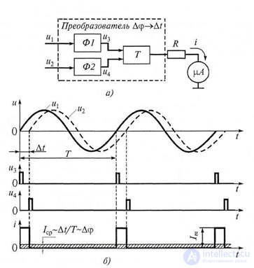
Figure 5.6 The method of converting the phase shift into a time interval:
a) measurement scheme; b) signal plots
The pulses, acting on the resistor R, connected to the measuring device - microammeter μA, are converted into a sequence of current pulses i with the same period and duration and amplitude Im (see Fig. 5.6, b). As a measuring instrument, a microammeter of the magnetoelectric system is used, which reacts to the average value of current i over a period T. Let Icp be the average value of the current i flowing through the device. Then his testimony will be defined as:

α = Icp = T 1 ∆∫0 t Im dt = Im 360∆ϕ °, (5.13) where ∆φ is the measured phase shift.
The scale of the microammeter is calibrated directly in degrees. The measured value of the phase shift is average for the measurement time. The considered device is a direct reading phase meter. The range of its working frequencies is limited from below by the inertia of the magnetoelectric microammeter, and from above by the limb of the durations of the fronts of the formers that affect the trigger T operation. Analog phase meters measure the phase shift of signals in the frequency range 20 ... 106 Hz with an error
± 1 ... 20.
5.2.4 Digital phase meters
Most digital phase meters are close in principle to digital time interval gauges and operate on a discrete counting method. The discrete counting method (more precisely, the digital phase shift measurement method) used in digital phase meters includes two operations: the transformation of the phase shift into a time interval and the measurement of a time interval by the discrete count method.
The block diagram of the digital phase meter, which implements the discrete counting method, contains the converter of the desired phase shift Δφ in the time interval Δt (Δφ -> Δt), time selector VS, shaper of counting pulses f / nf, counter MF and digital readout device of the control center (Fig. 5.7, but).
The time selector is a key logic circuit. The shaper of counting pulses is based on the multiplier of the frequency of the input signal and the circuit for the formation of output pulses.
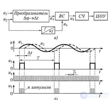
Figure 5.7. Digital phase shift measurement method:
a - block diagram; b - time diagrams
Digital phase meter works as follows.
The Δφ → Δt converter from sinusoidal signals u1 and u2 fed to its inputs with phase shift Δφ forms a sequence of rectangular pulses u3 (Fig. 5.7, b) having a duration Δt and a repetition period T equal to respectively the time shift and the period of signals u1 and u2 . The pulses u3, as well as the counting pulses u4, produced by the shaper of the counting pulses, are fed to the inputs of the time selector. The selector is opened for a time equal to the duration Δt of the pulses u3, and during this interval it transmits the pulses u4 to the counter input. At the output of the selector, pulse packets u5 are formed, which follow with a period T.
The measurement is carried out in one period T of the sequence of signals u1 and u2 (the control circuit providing such a measurement mode is shown in Fig. 5.7, but not shown for simplicity). In this case, the counter from the output of the selector receives the number of pulses Contained in one package:
n = Δt / That /, (5.14)
In digital phase meters, the repetition pulse period of the driver for the convenience of circuit implementation is T0 =
T / (36 · 10m), m = (1, 2, 3 ...).
The expression for the measured phase shift of the signals u1 and u2: n
∆ϕ = 10 m −1, (5.15)
The phase shift Δφ is proportional to the number of counting pulses n received at the counter. The code signal from the counter, proportional to the phase shift Δφ, is fed to the central processing unit, whose readings are given in degrees at m = 1, taking into account tenths of a degree at m = 2, etc.
The error of this digital phase meter is determined by the errors of discreteness and equipment. The error of discreteness is due to the fact that the time interval Δt can be changed with an accuracy of one period of counting pulses. The instrumental error is determined by the deviation of the duration from Δt, the instability of the transducer Δφ -> Δt, etc.
1. What is called a phase shift?
2. List the oscillographic methods for measuring the phase shift.
3. Explain the application of the linear sweep method to measure the phase shift.
4. Determination of phase shift by the ellipse method.
5. The method of converting the phase shift in the time interval.
6. Explain the operation of the digital phase meter.

Comments
To leave a comment
METROLOGY AND ELECTROradio-measurement
Terms: METROLOGY AND ELECTROradio-measurement