Lecture
When measuring at a direct current and if there are serviceable wires that can be used, the distance to the grounding point of one of the wires can be found according to a scheme similar to fig. 8.2, only grounding (after some contact resistance Rn) should be transferred to some point on the wire, say R2 (instead of artificially created grounding when measuring asymmetry at the end of the loop). It is possible to use the bridge scheme with a variable shoulder ratio (Murray scheme, Fig. 7.16). For this scheme, the equilibrium condition is determined by the expressions rarx = rb (Rthm - rx) and:
rx = Rthread [rb / (ra + rb)], (7.1)
If the wires L1 and L2 are the same, then:
Lx = 2 l [ rb / ( ra + rb )], (7.2)
The dotted resistor rdob is used when the damage is very close to art. A and the balancing of the bridge is hampered by the need to supply too much of the resistance ra and ra. When using rdob (usually about 10-100 ohms), the value of 1 is found from the condition rа (rх + rdob) = rb (Rshl - rx) Measurement error due to a significant difference between ra and rdb will increase.
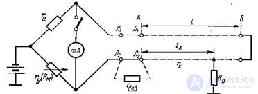
Figure 7.16 The Murray Scheme
It is important to note that the indicated methods of measuring 1X contain an uncertain error caused by the assumption that the resistance Rp at the site of damage is constant and that it is sufficiently small compared to the insulation resistance of wires L1 and L2 . If these values are commensurate, then the switching point of the generator diagonal of the bridge into the line turns out to be somewhat uncertain and the equilibrium conditions, written above, are somewhat violated. Therefore, if possible, it is recommended to determine the distance to the site of damage repeatedly, using several methods from both stations, and to judge the required distance by comparing the results of all measurements.
The formulas given for determining the 1X values are unsuitable if a wire with a quality different from the damaged one is used as a working wire, or if the damaged wire itself is between stations A and B is heterogeneous. In these cases, the distance 1X must be determined (based on the found value of rх), keeping in mind the structure of the formed plume. In addition, if it is possible to use any two wrong drives, then 1X can be found by using two and three measurement methods.
In case of damage to the insulation between the wires (messages over the wires between them through some transient resistance Rп), when there is a third, healthy wire, the distance to the damage can be quite simply determined by the schemes of Murray or Varley. In fig.
7.17 given the scheme Varley.
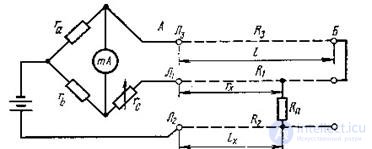
Picture. 7.17 Determining the distance to the place of the message wires in the presence of the third good wire
In the bridge circuit with a constant shoulder ratio, turn on a loop composed not of a damaged pair of wires, but formed of a working wire Rz and one of the wires of a damaged pair (in Fig. 7.17 - R1). The second wire of the damaged pair is used to create a generator diagonal. If the contact resistance Rn is large, then the battery voltage can be increased to 100 or even 500 V. From the equilibrium condition ra (rc + rx) = rb (Rsll - rx), there is a value:
rx = (rbRthis - rarc), (7.3)
where Rsll - the sum of the resistances of the wires R1 and R3 . If you take ra = rb, then
rx is found by a simpler formula:
rx = (Rsl - rc) / 2, (7.4)
The value lx is determined from the expression:
Lx = rx / rkm, (7.5) where rkm is the resistance of a kilometer of wire R1, taken for the temperature at which rx was measured. The value of Rsl are found either by the values of the resistances of the wires R1 and R3, which are known on the basis of previously carried out measurements (also with temperature correction), or is measured, for which purpose in the diagram in fig. 7.17 it is enough to disconnect the R2 wire from
clamp L2 and connect the latter with clamp L1.
The absence of corrected wires makes it difficult to determine the location of the insulation damage, causes noticeable measurement errors and requires careful examination each time, in as many ways as possible. It is especially difficult to find in these cases the desired distance when Rp is large and all the more variable.

Comments
To leave a comment
METROLOGY AND ELECTROradio-measurement
Terms: METROLOGY AND ELECTROradio-measurement