Lecture
Modern solutions in the field of industrial automation require the rejection of highly specialized solutions in favor of the wide use of personal computers equipped with ADC / DAC boards, digital input / output information, instrumentation, as well as various serial and parallel interfaces - interfaces. Such personal computers operating in real-time mode (on-line) can perform all the functions of specialized equipment, while preserving the advantages of a general-purpose computer, first of all, flexibility and adaptability of the interface.
The concept of “virtual instruments” (Virtual Instruments) appeared at the junction of measuring, information and computer equipment. A virtual device is a combination of a computer, universal hardware I / O signals and specialized software, which, in fact, determines the configuration and operation of the complete system. In fact, in the hands of the creator of the system there is a designer (set), from which even an engineer or researcher not experienced in computer technology can build a measuring device of any complexity. Now, rather, the task requirements and the corresponding software, rather than the capabilities of the instrument, determine the functional characteristics of the finished instrument.
In the simplest case, a virtual device is a personal computer combined with the appropriate software and a special data acquisition board installed in it (in an ISA or PCI slot) or external device connected via an LPT port, as well as through modern external interfaces. Such interfaces can be USB, RS-232, FieldBus, FireWire, IrDA, GPIB, etc.
A personal computer simulates the controls of a real device and performs its functions, which allows an engineer who knows how to work with this device to continue working with its virtual counterpart. A virtual device can contain only those indicators and controls that are necessary to solve the problem. At the same time, specialists can be trained on virtual analogues of real equipment, saving its resource and not putting it at risk of failure due to operator errors.
The distinctive features of virtual devices compared to microprocessor-based devices include:
• An extensive collection of standard applied computer programs available to the operator, allowing to solve a wide range of applied measurement tasks (research and processing of signals, data collection from sensors, control of various industrial installations, etc.);
• the ability to quickly transfer research and measurement data over local and global computer networks (for example, the Internet);
• a highly developed graphical user interface that provides rapid mastering of interaction with the system;
• the possibility of using internal and external high-capacity memory, as well as compiling computer programs for solving specific measurement tasks;
• the ability to quickly use various devices for documenting measurement results.
Virtual Instrument Architecture
A virtual device can be built in two ways: with a serial or parallel architecture.
In a virtual instrument with a sequential architecture (it is sometimes called a centralized system), parts of the system that convert the analyzed signals process them in a sequential mode. Therefore, all relevant electronics are placed on the slots of the computer.
A virtual device with a parallel architecture contains a number of parallel measurement channels, each of which has its own conversion nodes for the analyzed signals and only the computer processor operates in multiplexing mode (i.e. signal combining). This principle of building a virtual instrument allows optimization of signal processing in each channel independently. In such a system, signal conversion can be performed locally at the location of the source of the signal under study, which allows transmitting signals from the object being measured in digital form.
A generalized block diagram of a virtual instrument, reflecting both architectures of construction, is shown in Fig. 2
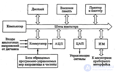
Figure 2
The interaction between the individual elements of the virtual device is carried out using the internal bus of the computer, to which both its external devices (display, external memory, printer, plotter) are connected, as well as a measuring circuit consisting of a switch, ADC and a block of exemplary software-controlled voltage measures and frequencies. Using a DAC, you can generate control analog signals; The IM interface module connects the meter to the instrument interface trunk. The device switch provides the supply of analog voltages from external sensors to the system nodes. Quite simple virtual instrument nodes can be placed on a single PC board. There are also more complex structures of virtual instruments, in which, in accordance with the measurement task to be solved, the architecture of the system is changed according to the installed program.
One of the elements of a virtual instrument is a block of exemplary software-controlled measures of voltage and frequency. In virtual devices, it is possible to determine individual functions of the effect of temperature on various parameters of the device: the zero drift of the DCF, the transfer coefficients of various elements. Continuous monitoring of the temperature of the blocks allows you to automatically adjust the resulting measurement errors.
The main role in virtual instruments is played by data acquisition boards with the necessary metrological characteristics for this task, such as the ADC resolution, speed and dynamic errors of the analog-digital channel. It is necessary to use fast and efficient algorithms for processing the measured information, to develop a convenient program for collecting and displaying data for the most common operating systems Windows 2000, NT, XP, etc.
One of the most famous among the specialists in the development of virtual instruments is the LabVIEW, BridgeVIEW and LookOut systems from National Instruments (USA). In addition, there are a large number of third-party virtual instrument libraries. Programs in LabVIEW are called virtual instruments, since the way they communicate with them resembles real instruments. Virtual instruments play the same role as functions in ordinary programming languages.
Replacing a textual representation with a graphical representation makes the measurement data and procedures more visual, does not create a language barrier, the figure expresses the meaning of information in more compact units; for example, this applies to Lab VIEW graphics software. The LabVIEW package — a graphical alternative to conventional programming — is designed to create an IC and is the software that is required when working in the area of monitoring, testing, and measurement. Using LabVIEW, you can create graphical programs — virtual instruments, instead of writing traditional programs.
The user of the virtual instrument includes a graphical panel object using a keyboard, a “mouse”, or a specialized application program. Virtual instruments combine large computing and graphics capabilities of a computer with high accuracy and high-speed ADC and DAC used in data acquisition boards. Essentially, virtual instruments perform an analysis of the amplitude, frequency, and temporal characteristics of various radio engineering circuits and measure the parameters of the signals with the accuracy of the applied ADC and DAC, and also generate signals for the measurement process itself and for automation of the IC.
The software part of the virtual instrument can emulate (create) on the computer display screen a virtual front control panel of a stationary measuring instrument. The control panel itself with virtual buttons, knobs and switches, formed on the display screen, becomes the virtual instrument control panel. Unlike a real control panel of a stationary measuring device, a virtual panel can be repeatedly rebuilt during operation to adapt to specific experimental conditions. Depending on the board and software, the user receives a measuring instrument for a particular metrological task.
Several years ago, a new promising direction appeared on the path of the development of programming technology and the creation of virtual instruments. It is called IVI (Interchangeable Virtual Instruments - interchangeable virtual instruments). The basic idea is this. All devices of one class have a large group of functions common to all devices, for example, all digital multimeters (DMM) measure direct and alternating voltage, resistance, and also perform other functions. If these functions are identified in the IVI Class Driver for the DMM Class, then the part of the program responsible for controlling the digital multimeters will not depend on the specific device and its driver. It should be noted the high quality and reliability of the device drivers VXI "Plug & Play", which is not related to the concept of classes of IVI Class Driver drivers, but is implemented by other means.
And of course, modern software systems are unthinkable without remote access. It is difficult to imagine a responsible system that does not have access to the Internet.
Consider one of the modern virtual digital storage oscilloscopes. The appearance of the software user interface (virtual graphic measuring panel) of a digital virtual oscilloscope is shown in Fig. 3
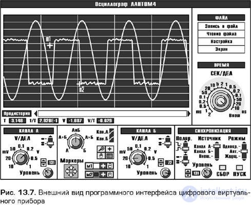
Figure 3
A virtual digital storage oscilloscope is designed for monitoring, recording, long-term storage, analysis and measurement of amplitude and time parameters of various pulsed, periodic and random processes. The software oscilloscope, stored in the computer's memory, communicates with the data acquisition board on the readiness of the device for processing information. After issuing a special command to the board to collect data on the parameters of the signals under study, the program expects a message from it about the completion of the procedure for filling the buffer memory built into the data acquisition board. Then the analyzed signals are sent to a computer, where the processor completely processes and analyzes them. Software files allow you to document the processes under investigation using a computer, compare signals with reference ones, and display signals created by the user in his programs.
The principle of the data acquisition board is simplified as follows. The data collection process can be divided into two stages: recording digitized signals into the buffer memory of the data acquisition board (corresponds to the return path of a real oscilloscope) and transferring data to a virtual oscilloscope, processing them and outputting to the screen (corresponding to the direct course of a real oscilloscope). The “direct beam path” mode (image refresh interval on the screen) depends on the memory capacity of the acquisition buffer of the data acquisition board, processor speed and computer RAM, and the number of oscilloscope channels.
Despite the fact that the signals under study are analog, the image on the virtual screen (computer display) of the oscilloscope is formed after analog-digital conversion and therefore is discrete. Virtual buttons, knobs, switches and other GUI elements are almost the same as the real ones. The only and main difference between them is the change in the position of the knobs and switches, which is carried out with the help of a “mouse” (or keyboard), and not with a hand, like with real measuring instruments.
The advantages of the considered virtual digital storage oscilloscope:
• high accuracy of measurements of parameters of signals or circuits;
• a bright, well-focused screen at any sweep speed and sharply outlined contours of the image;
• high bandwidth;
• the ability to memorize a signal plot for an arbitrary time;
• automatic measurement of signal parameters;
• the possibility of statistical processing of measurement results;
• availability of means of self-calibration and the ability to compare current data with model or pre-recorded;
• availability of printer and plotter to create a report on the results
measurements, as well as simplified archiving of measurement results;
• the possibility of studying transients occurring
in electrical circuits.
In fig. Figure 4 shows the appearance of the software interface of a virtual digital spectrum analyzer, and fig. 5 - virtual digital signal generator.
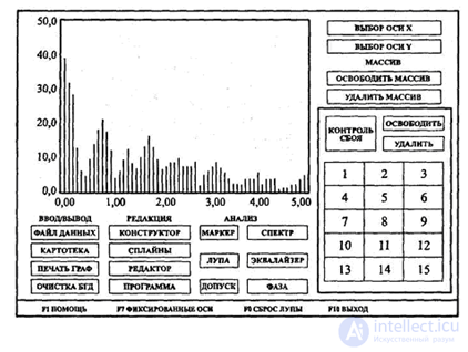
Figure 4. The appearance of the virtual software interface
digital spectrum analyzer
A virtual spectrum analyzer can examine from 2 to 1024 harmonic components and allows you to calculate the amplitudes and phases of the harmonics, as well as the Fourier coefficients of the spectral representation of the signal under study.
The TsGS-31 virtual signal generator is capable of creating a wide grid of frequencies and has many operating modes that allow you to adjust various parameters of the output signals.

Figure 5. The appearance of the virtual software interface
digital signal generator
So, the extensive computational capabilities of virtual instruments make it possible to implement many methods of improving measurement accuracy, efficiency, and speed using software methods. For example, if the measured histogram of the distribution of a physical quantity, observed by an experimenter on a computer display, has fallen out values and a smoothed form, then one should assume the existence of outliers and the presence of a drift in the measured value or error. To eliminate emissions, you can use one of the statistical programs.
Currently, the direction is being developed for the development of virtual measurement systems that widely use the capabilities of modern computers, computer graphics, advanced measurement methods and tools, digital information processing, and effective “Plug & Play” multimedia technologies in creating software and technology. On the basis of such systems, experimental: scientific measurements and research are carried out in the form of universal (functionally oriented) instruments in a virtual design (oscillographs, analyzers, generators, signal synthesizers, multimeters, voltmeters, frequency meters, multiplexers, etc.) and special (problem-oriented). a) systems used in spectroscopy, acousto-and superconducting electronics, in polarized studies of optical LEDs, the study of the propagation of electromagnetic radiation in gases and atmosphere, remote sensing of the Earth and planets, etc .;
• development of a family of new universal computer devices synthesized by software, among which devices can be distinguished with a unit for evaluating and presenting the accuracy of instrument characteristics and measurements;
• creation of virtual educational systems: workshops and simulators, electronic catalogs and instructions for mass-produced devices, built on adequate models of devices.

Comments
To leave a comment
METROLOGY AND ELECTROradio-measurement
Terms: METROLOGY AND ELECTROradio-measurement