Lecture
3.2.1 Measuring LC Generators
In LC generators for which the conditions of balances are fulfilled
amplitudes and phases, the frequency is mainly determined by the resonance of the oscillating circuit:
f = 1, (3.3)
 2π lc
2π lc
Simplified diagram of the LC-generator on the operational amplifier
shown in fig. 3.4, a. The self-oscillator amplifier is covered by two feedback circuits that provide amplitude and phase balance modes. The amplitude balance is established by a negative feedback circuit consisting of resistors R1 and R2 . With its help, set the required gain of the actual amplifier | K | = R2 / R1 . The balance of the phases is provided by a positive OS circuit consisting of a resistor R and a parallel oscillating LC circuit. Positive OS Chain Transfer Ratio
 β = R 0, (3.4)
R 0 + R
where RQ is the resonant resistance of the parallel circuit.
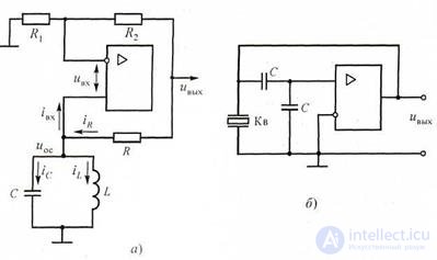
Figure 3.4 Schemes of LC-generators at the OS:
and - the simplified electric; b - with quartz stabilization
In the range of radio frequencies in measuring instruments, both signal generators and standard signal generators are used. Signal generators have a large average output power (up to 3 W) and are used to power measuring transmitting antennas and other powerful devices. Generators of standard signals - low-power sources with a low level of output voltage (up to 1 V) - are used for testing and tuning of radio equipment nodes. The main requirements for the GSS: high stability of the frequency and amplitude of the output signal, a small coefficient of nonlinear distortion. Generators of standard signals provide for the possibility of obtaining amplitude modulation by using both external and internal voltage sources. Internal modulation usually operates at frequencies of 400 and 1000 Hz.
3.2.2 Characteristics of microwave generators
Ultra-high-frequency generators (microwave generators) operate in the frequency range 1 ... 40 GHz. According to the type of output connector with the studied circuit, they are divided into coaxial and waveguide, with the latter more high-frequency. For microwave generators, a single-band construction is typical, with a small frequency overlap (about an octave - 2 times). The uncalibrated output power of the measuring microwave generator reaches ten watts, and the calibrated one is several microwatts. Scales of calibrated attenuators of microwave generators are calibrated in dB, and GSS - in decibels and microwatts.
Ultra-high-frequency generators are used to tune radio receivers of radar and radio navigation stations, space communications and satellite broadcasting systems, measure parameters of various antennas, etc. The block diagram of the microwave generator is shown in Fig. 3.5. The features of measuring generators of this type are the relative simplicity of the electronic part of the circuit and the complexity of the mechanical components of the devices. The circuit includes the microwave generator itself, a pulse modulator, a low-power meter, a frequency meter and a calibrated attenuator. All high-frequency nodes of the generator are connected by waveguides.
Specific microwave generators of measuring devices are performed on reflective klystrons, Gunn diodes, magnetrons, avalanche-span diodes (LPD), traveling lamps (TWT) and backward waves (BWO), etc.
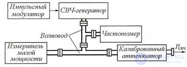
Figure 3.5 Block diagram of the microwave generator
In measuring microwave generators, careful shielding is necessary, since the power leakage increases with increasing frequency. The power wires are made in the form of coaxial cables with a special filling that absorbs the energy of microwave oscillations well. Increased demands are also made on power supplies, since the active elements of the microwave range are sensitive to the instability of the supply voltages.
1. What are the features of the design of microwave generators?
2. Explain the operation of the LC generator.
3. Explain the need for careful screening in microwave generators.
4. What is the oscillation frequency of the LC-generator?

Comments
To leave a comment
METROLOGY AND ELECTROradio-measurement
Terms: METROLOGY AND ELECTROradio-measurement